29. Light waves
Summary
Light models
So far, we have discussed how light travels by treating it like a ray. A beam of light travels from one place to another, and along the way it might bounce (reflect) or bend (refract). Possibly it might transmit or be absorbed. This simple model of light explains a lot: mirrors, lenses, rainbows, and other phenomena we’ve discussed in the past few chapters of this textbook. This model of light is known as ray optics.
Ray optics is great in its simplicity, but there are aspects of light that cannot be explained by this model. We can expand our model to include the wave nature of light. This new model is known as wave optics. Treating light as a wave allows us to understand and quantify phenomena such as interference and diffraction.
If we wish to expand our view of light even more, we can use the model of electromagnetic optics. This takes the wave nature of light into account, but also includes the fact that light is composed of electric-field and magnetic-field vectors oscillating in space. An electromagnetic approach to optics explains and quantifies phenomena such as light polarization.
Finally, a fully quantum model of light, quantum optics, can be used to explain all of the above phenomena, plus phenomena such as the photoelectric effect, lasers, semiconductors, and more. This is the most complicated and mathematically rigorous model of light, used to explain complex phenomena when the other models fall short. We will discuss some of these fascinating topics in a later chapter of this textbook, but will not go into a full mathematical treatment of quantum optics.
|
light model |
phenomena |
|
ray optics |
reflection, refraction, dispersion |
|
wave optics |
interference, diffraction |
|
electromagnetic optics |
polarization |
|
quantum optics |
photoelectric effect, lasers, semiconductors |
Huygens’ principle
In 1690, a mathematical theory of light by Christiaan Huygens was published. Huygens’ proposal of how light propagates is known as Huygens’ principle. Huygens’ principle states that every point on a wave can be treated as a source of a spherical wave that itself propagates through time and space. Each of these individual spherical waves interacts with the others through interference. Each individual spherical wave amplitude is added to the amplitude of every other individual spherical wave, and that sum total represents the total wave. Note that Huygens’ principle is a simplified model that we can use to understand some concepts, but it is not a complete theory of optics or electromagnetism.
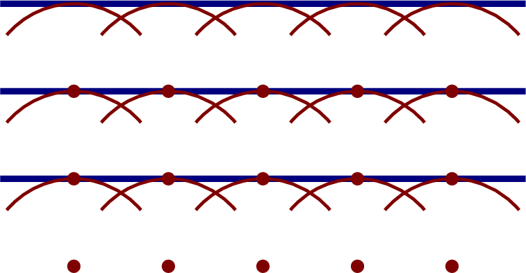
For example, a plane wave is a light wave that travels through space with all of the wave crests and troughs aligned in straight lines. If we want to draw a plane wave, we can draw a line where the wave crests are, and note that they form parallel lines in space. A plane wave is a very simple type of wave to analyze mathematically, and is a nice approximation that physicists and engineers can use in optics calculations. Huygens’ principle says that we can represent each point on each wave crest in the plane wave as a spherical wave. The interference of those spherical waves causes what we see as a plane wave. This is shown in Figure 29.1. Note that the figure shows only five representative points. However, Huygens’ principle states that every point (of which there are an infinite number) acts as a source of a spherical wave whose constructive interference effect gives rise to the next wavefront.
Huygens’ principle is particularly useful in describing what happens when light passes through a narrow opening. A plane wave traveling through a narrow opening will curve at the edges when it passes through. Because Huygens’ principle describes light as a collection of spherical waves, it provides a description of that spherical shape at the edges. This is shown in Figure 29.2.
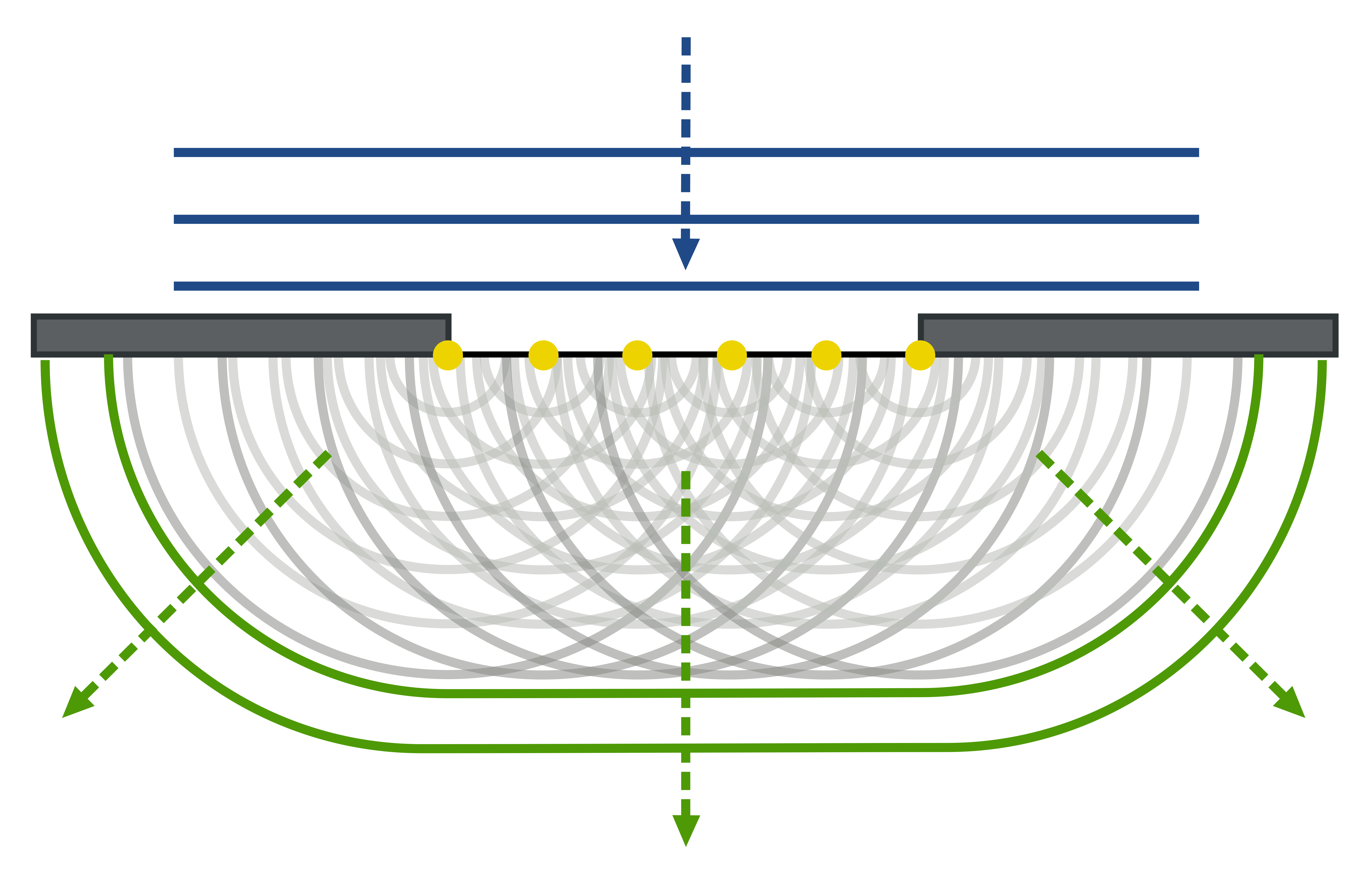
The amount of curving relates to the wavelength of light traveling through the opening as well as the width of the opening. The larger the width of the opening as compared to the wavelength of the wave, the less pronounced the curving of light will be. The smaller the width of the opening as compared to the wavelength of the wave, the more pronounced the curving of light will be.
Diffraction
Diffraction is a bending of light (or, in general, any wave) as it travels around a corner or through a narrow opening, as previously discussed using Huygens’ principle as a model. Diffraction can occur with all waves, but only creates a noticeable effect when the width of the opening is on the same size scale as the wavelength of the wave.
Diffraction occurs not only with visible light, but all waves, including water waves. In addition, diffraction occurs with all types of electromagnetic waves, not just visible light. Radio waves, for example, will diffract around buildings, mountains, and other terrain.
The amount of bending that occurs in diffraction has to do with the wavelength of the light. The longer the wavelength, the more bending will occur, with all other things being equal. In this manner, diffraction can be used as a technique to split polychromatic light (light composed of multiple wavelengths of light) into its constituent components.
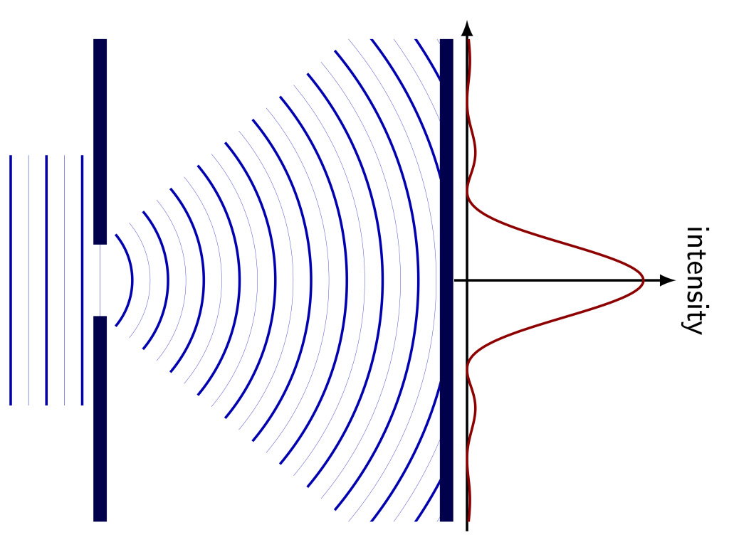
When light travels through a narrow opening and gets diffracted, that light can then be collected and measured. The intensity of this light creates a pattern, known as a diffraction pattern. When light diffracts through a single slit, the diffraction pattern appears as shown in Figure 29.3. There is a broad peak in intensity opposite the opening, with some smaller peaks appearing at regular intervals, eventually reducing in intensity to zero. The mathematics behind this pattern is complicated, but in general terms, the broadness of the peak and distance between peaks have to do with the width of the slit, the wavelength of the light, and the distance away from the opening where the light intensity is measured.
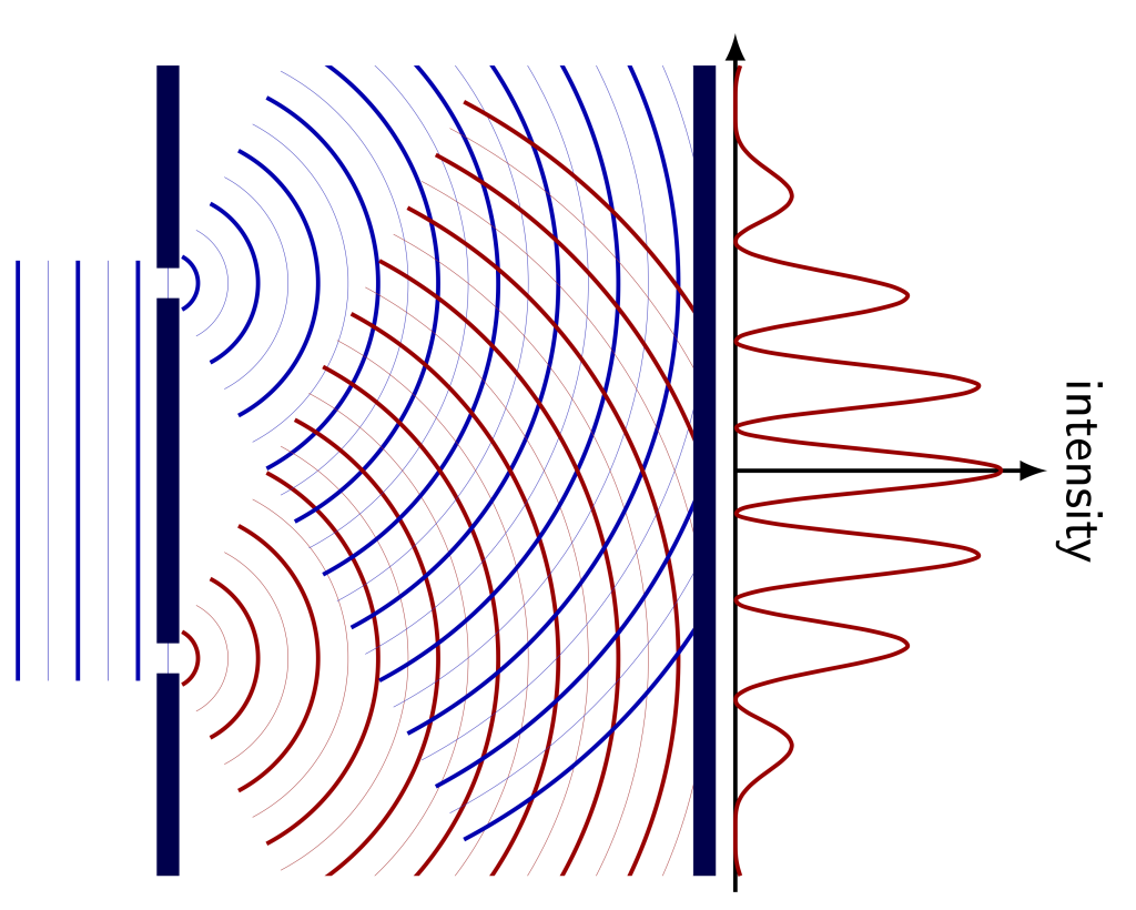
When a second slit is introduced close to the first, it is known as a double slit. The diffraction pattern now shows a more pronounced periodic spacing between areas of constructive interference when measured. This particular pattern arises due to a combination of diffraction from the slits and the interference between the two waves. This is shown in Figure 29.4.
A diffraction grating is a component that has regularly spaced narrow openings for light to pass through. By spacing these openings periodically, light at different wavelengths will get diffracted through at different angles. This technique is particularly good at splitting polychromatic light into its constituent components because the periodic spacing between the openings will create regions of constructive and destructive interference for each wavelength.
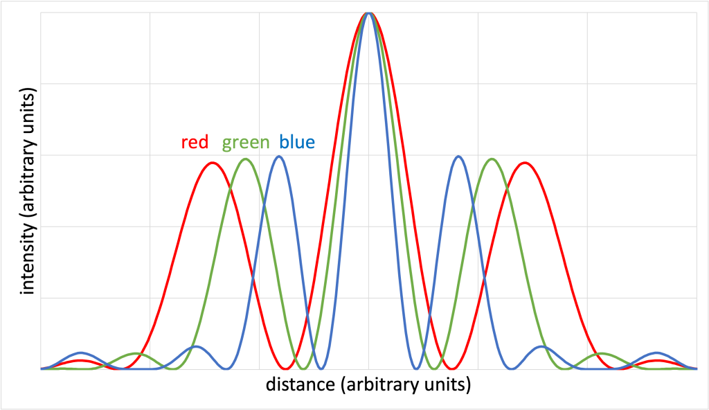
The exact locations where constructive and destructive interference occurs depends on the wavelength of the light. It turns out that the longer the wavelength, the farther apart the regions of constructive and destructive interference. The graph in Figure 29.5 (Download this data [XLSX, 25 kB]) shows the intensity of a double-slit diffraction pattern for red, green, and blue light as it would appear on a screen a certain distance away from the openings. Red light (which has the longer wavelength) has constructive interference peaks spaced farther apart than green light (which has a shorter wavelength than red). Blue light (which has a wavelength shorter than the two other colors) has the smallest spacing between the interference peaks.
While both diffraction gratings and prisms are capable of splitting polychromatic light into its individual components, a diffraction grating typically spreads the components of light into a greater range of angles than a prism. This allows us to more accurately determine the intensity of each wavelength of light than is possible when using a prism. (In other words, because the light is spread over a greater number of angles, it is possible to get more detail in between each particular angle.)
In the video below, Dr. Pasquale demonstrates the effect of different color (wavelength) light as it is sent through a diffraction grating that has 1000 openings per millimeter. First, she shines a blue laser pointer through the diffraction grating. On a screen 1 meter away, we can observe each of the bright spots indicating points of constructive interference. Dr. Pasquale used a ruler to measure the distance between each spot, which is 46 cm.
When she then shines a green laser pointer through the diffraction grating (keeping all other variables the same), the spots are now spread farther apart: 65 cm. This is because the larger wavelength of green light as compared to blue light, given the same spacing on the diffraction grating, will cause the light to spread more.
Repeating the experiment with a red pointer gives the largest distance between spots: 90 cm. Red has the longest wavelength of visible light, and will therefore spread the most.
In the video below, Dr. Pasquale repeats this demonstration using a different diffraction grating. This one contains 500 openings per millimeter, which means that each opening is wider than in the previous demonstration. This time, the blue laser pointer spreads apart 20 cm, the green laser pointer spreads apart 27 cm, and the red laser pointer spreads apart 36 cm. The same relationship between wavelength and diffraction angle is demonstrated. The larger the wavelength, the larger the diffraction angle (assuming the size of the diffraction grating is kept constant).
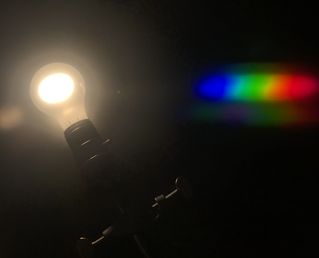
It’s also possible to shine a white light source on a diffraction grating and see what happens. Because white light is composed of all other colors of light, we can observe each color getting split apart due to the different amounts of bending based on wavelength. When shining white light through a diffraction grating, the longer wavelengths bend the most, and the shorter wavelengths bend the least. This results in a rainbow pattern. A photograph of an incandescent light bulb viewed through a diffraction grating is shown in Figure 29.6. Note that the constructive interference occurs to the right of the bulb in the photograph, showing the composition of the white light. (In particular, an incandescent light bulb contains a continuous spectrum of colors from red to violet, which will be described in the next chapter of this textbook.)
Diffraction gratings have lots of uses in physics and engineering. For example, when Dr. Pasquale was a graduate student, she would use a diffraction grating to determine how well different devices she designed in a clean room would emit different wavelengths of light. By focusing white light on the device, and taking the emitted light and sending it through a diffraction grating, each wavelength of light would be split apart. A recording device known as a CCD was used to measure the intensity of each wavelength. She could then use that recorded data to see what wavelengths of light her device emitted.
Scientists also use diffraction gratings to determine the composition of stars, including our Sun. By looking at the different wavelengths of light that stars emit, and understanding the concept of light emission that we’ll discuss later in this textbook, scientists can determine the elemental composition of stars.
One last thing about diffraction. Because light bends when it interacts with an opening, diffraction limits our ability to see really small things. This means that most imaging devices, such as cameras and microscopes, can only focus on things that are larger than about one half of the wavelength of light that’s used. If the smallest wavelengths of visible light are 400 nm, that means the smallest things that can be seen using a light microscope or camera must necessarily be larger than 200 nm. We cannot use visible light waves to see things smaller than that!
Thin-film interference
When light waves reflect at the top and bottom interfaces of a thin layer of material, an interference effect will occur. This phenomenon is known as thin-film interference. Light will reflect off of both the top and bottom surfaces of the thin film. Under certain conditions of wavelength and thickness, it is possible for these two reflections of light to constructively interfere. This is shown qualitatively in Figure 29.7.
It is also possible for destructive interference to occur in thin films. This occurs when the top and bottom reflections of light are out of phase with each other. This is shown qualitatively in Figure 29.8.
The relationship between the thickness of the film and wavelength to create conditions of constructive and destructive interference is complicated. However, generally speaking, the wavelength of light that will be affected has to do with the thickness of the film, the index of refraction of the film, and the angle that the light hits the film.
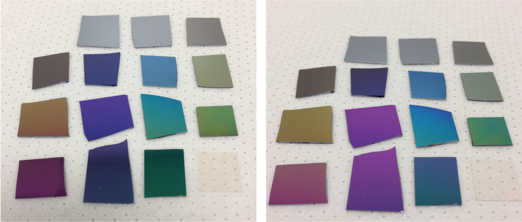
This is demonstrated in Figure 29.9. Dr. Pasquale deposited glass with different thicknesses onto silicon, which is highly reflective to visible light. In both photographs, each sample appears to be a different color based on the thickness of the glass. The colors of the samples in the left and right images are slightly different due to the difference in angle that the light hits the samples (the only difference between the two images is the viewing angle). Both photographs contain a sample that is only silicon with no glass on it, in the upper left, for reference. In addition, a sample that is only glass is shown in the bottom right, also for reference. (As these two reference samples do not contain any films on them, they do not look different at different viewing angles.)
This thin-film interference effect is very useful in optical applications. By layering multiple thin films, it is possible to create an anti-reflection coating. These are used frequently on eyeglasses, cameras, microscopes, and other optical devices.
Single thin films can be used to determine optical flatness. Using a light source that emits a single wavelength of light (known as monochromatic, as it only has one wavelength of light present), the presence of interference fringes (patterns of dark and light spots) can be used to determine the flatness of a gap between two surfaces.
If the gap between two planar surfaces is completely flat, the interference fringes will appear as periodic parallel lines. This is demonstrated in the video below where Dr. Pasquale uses a monochromatic light source shining on two stacked pieces of glass. When she pushes on the upper piece of glass, she changes the thickness of air between the two pieces of glass, and the interference fringes change their pattern.
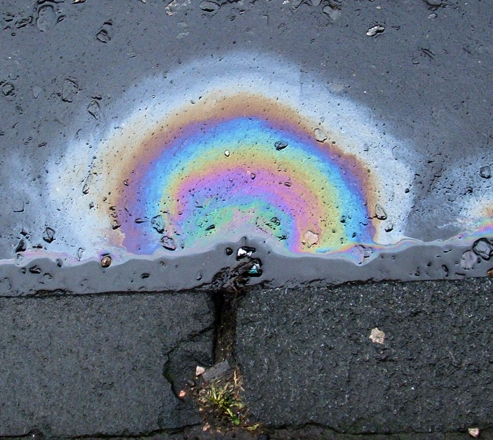
If instead of monochromatic light, polychromatic or white light is used to illuminate a thin film, the effect can be very colorful. This occurs, for example, on oily water puddles (as shown in Figure 29.10). In a thin puddle of oily water, a thin layer of oil will sit on top of the water. As the thickness of the oil changes at the edges of the puddle, the changing thickness and light interference result in a rainbow. This is also seen in soap bubbles and other similar phenomena.
Polarization
As mentioned, modeling light as a wave allows us to understand properties of light such as interference and diffraction. Expanding this model to encompass electromagnetism allows us to understand the property of polarization. Recall that light is composed of electric fields and magnetic fields oscillating at right angles to each other. (Note that the field components do not actually move up and down; instead, their intensities vary along dimensions that are at right angles to each other.) Light is a transverse wave, which means the direction of motion of the light wave is at right angles to these fluctuations in the intensity of the electric and magnetic fields.
Polarization is the property of transverse waves which allows them to have their electric field components oscillating in a single direction. Essentially, the electric fields that oscillate in a perpendicular direction to a device known as a polarizing filter can be blocked, allowing only a single orientation of waves to travel through space.
Note that polarization is not possible in longitudinal waves. To block the changes in intensity in a longitudinal wave, the entire wave motion would need to be blocked. The fact that light can be polarized means that electromagnetic waves are transverse.
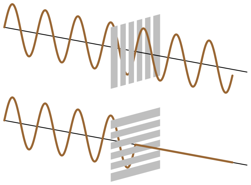
An analogy that can be used to conceptualize this is shaking a long rope up and down and seeing if it passes through a picket fence. When the orientation of the rope is parallel to the picket fence, it passes through (Figure 28.11, top). However, when the orientation of the rope is perpendicular to the picket fence, it is completely blocked (Figure 28.11, bottom).
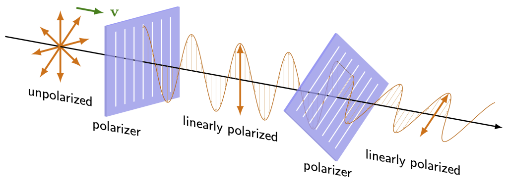
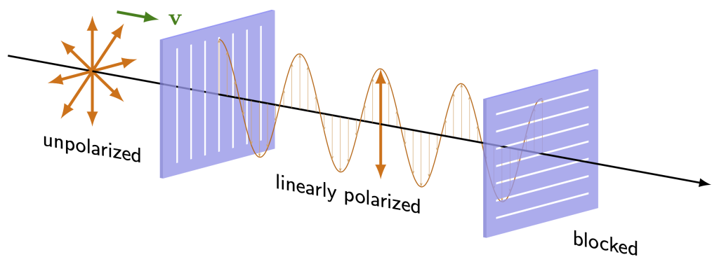
Many light sources generate light waves with all orientations of electric field oscillations, known as unpolarized light. This light can be passed through a linear polarizing filter, which only allows light of a certain orientation to pass through (all perpendicular orientations are blocked). This polarized light is known as linearly polarized, as the electric field of the light oscillates in a linear direction. Figure 29.12 shows unpolarized light passing through a polarizer and becoming linearly polarized. A second polarizer takes that linearly polarized light and once again changes its polarization to a different linear orientation.
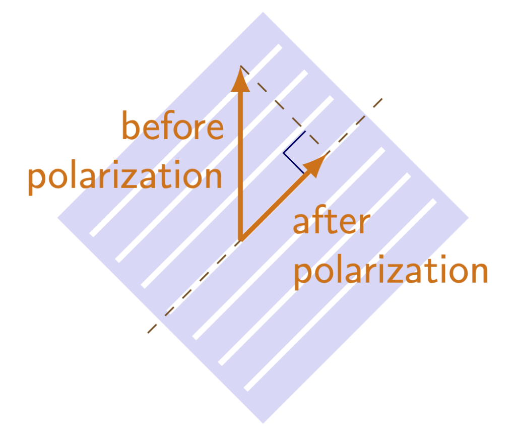
In general, the component of light that is parallel to a polarizer’s orientation will be able to pass through. Qualitatively, this means that, for two polarizers at different angles from each other, intensity will be reduced every time light passes through a new polarizer. (This textbook will not consider this value quantitatively, as it requires trigonometry to do so.) Figure 29.13 demonstrates how light exhibiting a single orientation of polarization can be broken down into components that are parallel and perpendicular to a polarizer. The polarizer blocks the perpendicular component. (Earlier in this textbook when discussing work, we had to calculate the parallel component of a force. This is somewhat similar in that we are calculating the parallel component of a particular orientation of light.)
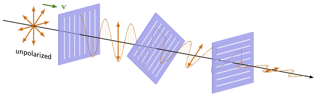
If a polarizer is completely perpendicular to the orientation of light, then there is no component that can pass through (as there will be no parallel component), and all light will be blocked. Any time two subsequent polarizers are placed at 90 degree angles to each other, light will be blocked. This is depicted in Figure 29.14.
However, if a third polarizer is placed between the two perpendicular polarizers, it is once again possible to have light pass through to the output. This is depicted in Figure 29.15. This is because there is always a parallel component to pass through each of the linear polarizers. The only way to completely block light with a polarizer is to have two subsequent polarizers at right angles to each other.
Dr. Pasquale demonstrates this effect in the video below. The demo starts with a single linear polarizing filter (filter A) between a light bulb and the video camera. A second filter (filter B) at a perpendicular orientation to filter A is then placed into the path, blocking the light from the light bulb. Dr. Pasquale rotates filter B through 180 degrees of rotation, demonstrating that the light will become brighter until filters A and B are parallel, and then become blocked again when filters A and B are perpendicular.
Then, Dr. Pasquale places a third polarizing filter (filter C) in between filters A and B. This filter is placed at a random angle (not perpendicular to either A or B) and light from the light bulb is no longer blocked. Dr. Pasquale rotates filter C through a broad range of angles, showing that it will block light when perpendicular to either filter A or filter B. When Dr. Pasquale removes filter C, the light is once again blocked.
Brewster’s angle
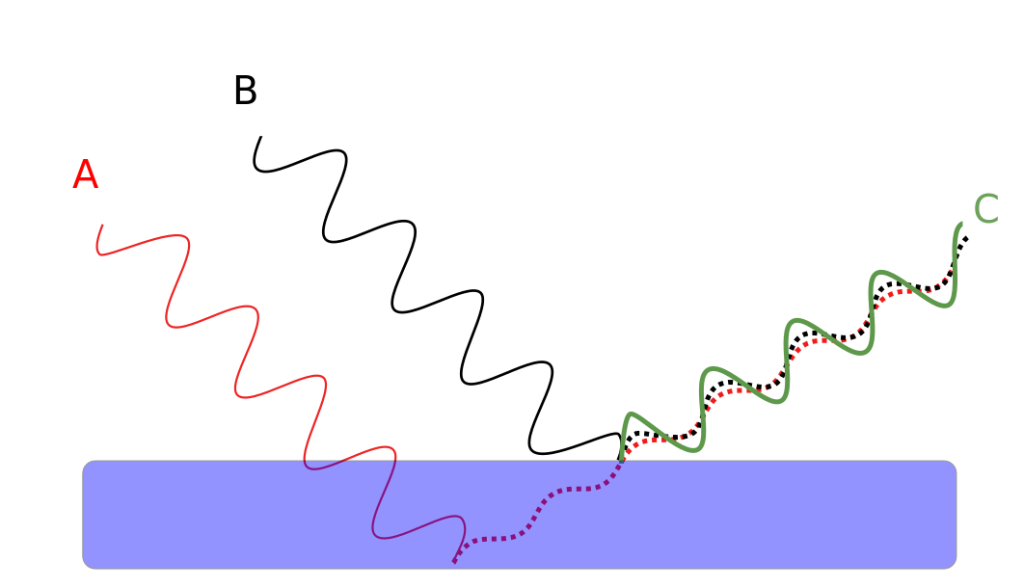
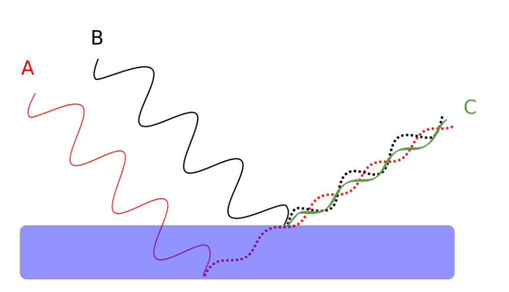
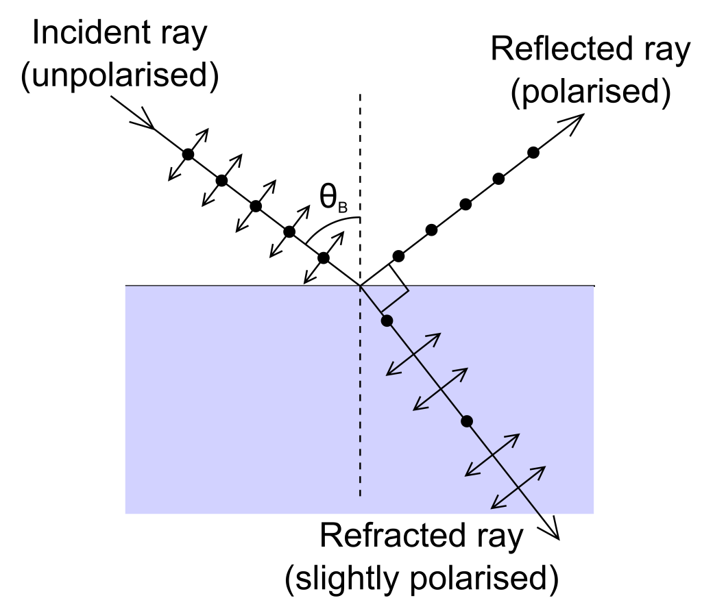
When unpolarized light reflects off of a surface at a particular angle, known as Brewster’s angle, the reflected light will be polarized 100% in a direction parallel to the reflecting surface. The light polarized perpendicularly does not reflect. At angles greater than the Brewster angle, the reflected light will still have both components, but the perpendicular component of polarization will always be less than the parallel component. This is shown in Figure 29.16. (In the figure, the ray of light containing dots and arrows depicts unpolarized light that contains some polarizations parallel to the screen/page, and some that are perpendicular to the screen/page. The reflected light, containing only dots, is polarized perpendicular to the screen/page. The refracted light contains a mix of both polarizations, but favors light parallel to the screen/page.)
This means that any polarizing filter that blocks that reflected light will partially eliminate glare from reflections that occur at angles greater than the Brewster angle. This is what polarized sunglasses are designed to do. Polarized sunglasses block the polarization of light that is not reduced by this effect, which can cut down on glare.
When wearing polarized sunglasses, it can be very obvious when you look at something that generates polarized light, such as LCD screens, as they will appear not to emit any light. By tilting your head 90 degrees while wearing polarized sunglasses, you can see polarization effects. Not only do LCD screens and monitors have polarization effects, but so do heat-treated windshields in cars.
Birefringence
Some materials have an index of refraction that changes based on the polarization of light. This means that light in one polarization will bend more than light at the cross polarization. These materials are known as birefringent.
A birefringent crystal placed over the word “Birefringence!” shows this property in Figure 28.17 by demonstrating the double image created by the crystal. One of the images is polarized in one orientation, and the other image is polarized in the opposite orientation.
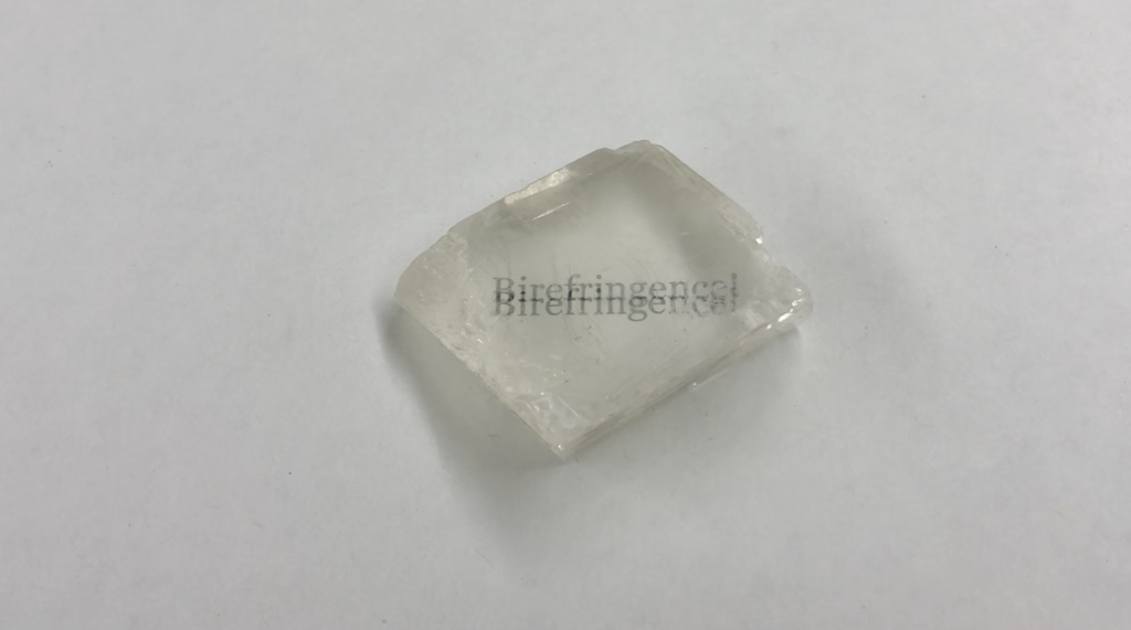
In the video below, Dr. Pasquale demonstrates the polarization of each component of the double image by rotating a polarizing filter over the piece of calcite. Depending on the orientation of the polarizing filter, one or the other of the images can be blocked.
Practice questions
Hands-on experiments
- If you own polarized sunglasses, use them to find examples of polarized light. Either rotate your head through 90 degrees while wearing them, or rotate the sunglasses through 90 degrees in front of your eyes. Notice if anything changes.
- Use a flashlight to bend light around a corner using diffraction. The instructions at this link will explain how.
A wave is a periodic oscillation that transfers energy from one place to another.
Interference is the phenomenon that occurs when two waves overlap. The total amount of wave energy present at a point is equal to the sum of each individual wave's energy at that point.
Diffraction is a bending of a wave as it travels around a corner or through a narrow opening.
A vector quantity is a variable that must be conveyed with both a numerical quantity (indicating magnitude or strength) and a direction.
Polarization is the property of transverse waves which allows them to have their electric field components oscillating in a single direction.
Quantum physics describes the physical laws used to describe the properties of matter and energy that occur on a very small scale.
The photoelectric effect is the emission of electrons when light of a particular frequency (especially UV light) strikes a metal target.
A theory is an explanation of how the universe works that is supported by multiple, repeated experiments.
Huygens’ principle states that every point on a wave can be treated as a source of a spherical wave that itself propagates through time and space. Each of these individual spherical waves interact with each other through interference, with the sum representing the total wave.
Wave amplitude describes the maximum displacement from either side of the equilibrium position.
Electromagnetism describes the interactions that occur between charged objects.
The wavelength of a wave describes the shortest distance between two identical repeating points on a wave. (symbol: λ, unit: m)
An electromagnetic wave is a transverse wave that contains electric and magnetic fields oscillating at right angles to each other.
Intensity describes the amount of energy per unit of area that reaches a certain location every second (unit: W/m^2)
Physics is a branch of science that focuses on the fundamentals of the workings of our universe.
An element is a substance that consists of atoms whose nuclei have the same atomic number. An element cannot be broken down further by chemical means.
Reflection occurs when a wave bounces off of a surface and subsequently changes its direction.
In a transverse wave, the vibrations of the wave travel perpendicular to the direction of motion of the wave.
In a longitudinal wave, the oscillations of the wave travel in the same direction as the wave itself.
Work is energy that is transferred to an object by exerting a force on that object over a distance. (symbol: W, unit: J)
A force is a push or a pull that causes an object to change its motion. More fundamentally, force is an interaction between two objects. (symbol: F, unit: N)
When unpolarized light reflects off of a surface at a particular angle, called Brewster's angle, the reflected light is polarized 100% in a direction parallel to the reflecting surface.
Heat is energy that is transferred from one object to another in response to a difference in temperature. (symbol: Q, unit: cal)
Birefringence is a property of some materials that causes the index of refraction to be different based on the polarization of light.
