28. Reflection and refraction
Summary
Every time you look in a mirror, take a photo, use eyeglasses, or look through a window, you’re experiencing reflection and refraction. Understanding how light travels enables us to grasp how the simple concepts of reflection and refraction affect our lives.
The principle of least time
Light travels from one point to another using the principle of least time. That is to say, light does not necessarily take the shortest distance between two points. Instead, it will travel whatever path takes the least amount of time. Sometimes, the path of least distance and the path of least time are the same. Other times, however, those two paths are not the same.
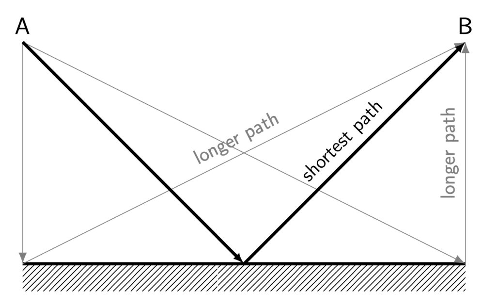
When light bounces off of a surface (such as a mirror), but otherwise travels through the same medium (such as air) throughout its journey, the path of least time is the same as the path of least distance. Because the speed of light through a single medium remains constant, the fastest path for light to travel will be the shortest path.
Consider light that starts at point A and bounces off of a mirror before traveling to point B (as shown in Figure 28.1). Any path that is not the shortest distance will take longer than the shortest path, due to the fact that time equals distance divided by velocity, and velocity remains constant through a single medium.
When light travels through different media, the path of least distance and the path of least time are no longer the same. We can use the lifeguard problem as an analogy to understand why this is so.
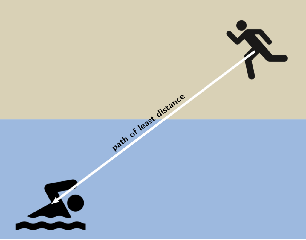
Consider a lifeguard on the beach. She sees a swimmer out in the water who needs help and may be drowning. The lifeguard needs to get to the swimmer as quickly as possible. She knows that she can run on the beach faster than she can swim through the water, so she wants to optimize her route to the swimmer to get to him as quickly as possible.
If the lifeguard takes a straight-line path to the swimmer, the path of least distance (shown in Figure 28.2), she will spend too much time in the water. Because she’s slower in the water than on the beach, this will not be the fastest route.
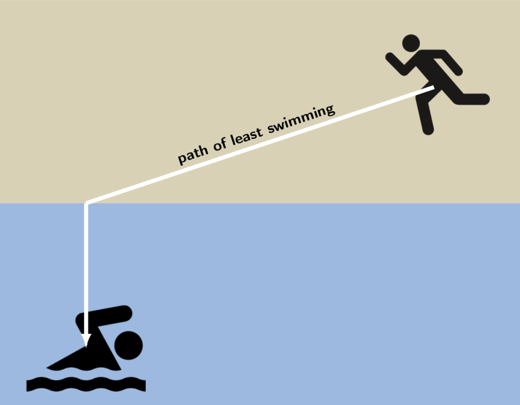
Alternatively, the lifeguard could minimize the amount of distance she spends in the water (shown in Figure 28.3), but this would cause her to spend too much time on land, which is also not an optimal route.
Depending on the lifeguard’s exact speeds in the land and in the water, her path of least time will be an optimization of more time on the beach and less time in the water, without making the overall path longer than it needs to be. A possible path of least time for the lifeguard is shown in Figure 28.4.
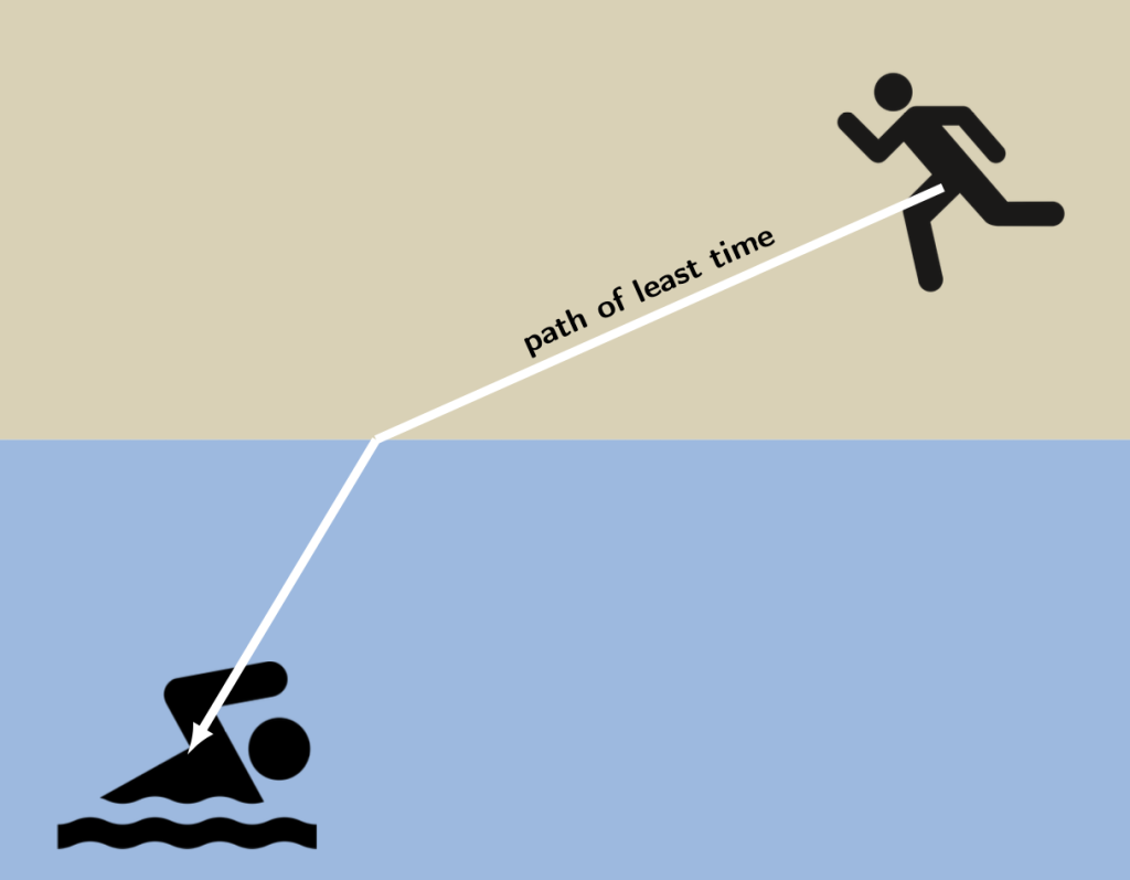
When the speed of light changes throughout its journey from point A to point B, the light will bend in order to travel the path of least time.
Reflection
Reflection is what happens when waves bounce off of a surface. As we learned in the previous chapter of this textbook, selective reflection and absorption of different colors of light is what makes opaque objects look a certain color. When white light hits something blue, the blue light reflects (bounces) back to our eyes, and red and green light is absorbed by the object.
The law of reflection tells us how exactly each ray of light moves when it bounces off of a surface. Due to the principle of least time, and because the speed of light stays constant in a single medium, the path of least distance will be equal to the path of least time. (In this case, we are making the assumption that light will be traveling through a single homogeneous medium, such as air or water, as it travels to and bounces off of a surface.) This leads to the law of reflection: the angle of reflection is equal to the angle of incidence. (The incident light is the light that hits the mirror, and the reflected light is the light that bounces off of the mirror.) In equation form, the law of reflection can be stated as

Angles are represented using the Greek letter theta ( ). In this equation,
  is the angle of the reflected light and
  is equal to the angle of the incident light.
When we talk about reflection and refraction, we measure angles with respect to the normal line. Wherever light is incident on a mirror, the normal line, at that point, is positioned at a right angle to the mirror’s surface. On a planar (straight-line) mirror this is a line that is perpendicular to the mirror’s surface everywhere on the mirror. On a curved mirror, the normal line will be perpendicular to the mirror’s surface at the point where the light hits the mirror.
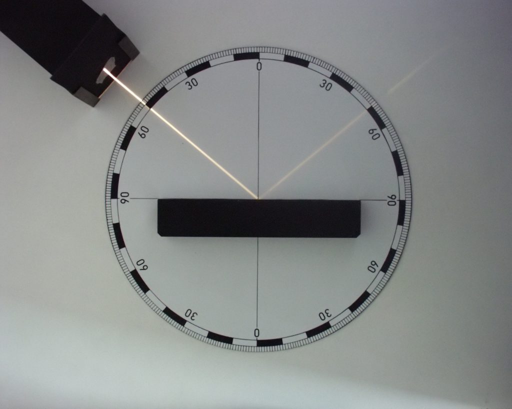
As stated above, when light hits a mirror at a spot, the angle of incidence is measured between the light ray and the normal line. The angle of reflection is equal to this angle of incidence. Therefore, if you know the angle of incidence, you can determine the angle of reflection by using the law of reflection: they are equal! In Figure 28.5, the mirror is planar and horizontal, and the normal line is depicted as a vertical black line at 0 degrees. The angle of incidence is measured between the normal line and the emitted light, which is 50 degrees. The angle of reflection is measured between the normal line and the reflected light, which is also 50 degrees.
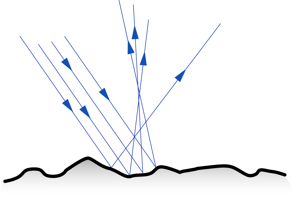
As previously noted, selective reflection is how different objects appear different colors. If reflection is occurring, why can’t we see our reflection in all objects that allow light to bounce off of them? The answer is that, while light always obeys the law of reflection, sometimes surfaces are rough enough that the light will bounce back in scattered directions. This type of reflection is known as diffuse reflection, and is depicted in Figure 28.6. It should be stressed that each individual ray still obeys the law of reflection in which the angle of incidence equals the angle of reflection relative to the normal. It is just that for a rough surface the normal line varies from point to point on the surface. (In contrast, light that bounces off of a smooth, polished surface, such as a mirror, is known as specular reflection.)
Mirrors
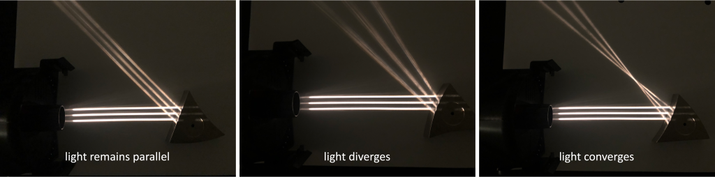
A mirror is a smooth reflective surface. Parallel rays of light that reflect off of a mirror can continue to travel parallel to each other, diverge (spread apart), or converge (come together) after reflection. These three scenarios are shown in Figure 28.7. Each ray of light reflects off of the mirror following the law of reflection. The converging or diverging property comes from the shape or curvature of the mirror.
When light reflects off of a mirror, the reflected light has properties that make it appear that those light rays were generated in a particular spot. For example, when we look in a bathroom mirror and see our reflection, that reflection occurs at a point where the reflected rays of light appear to have been generated. This reflection of ourselves, or of other objects, is known as an image.
An image is said to be virtual when the image is behind the mirror. A virtual image occurs when a mirror creates diverging rays of light upon reflection. Tracing these diverging rays backward (behind the mirror), the point where they come together is the point from which the reflected light appears to have been generated. The term “virtual” arises from the fact that no actual light from the object exists behind the mirror. A virtual image cannot be projected onto a screen.
An image is said to be real when the image is in front of the mirror. A real image occurs when a mirror creates converging rays of light upon reflection. The point at which the rays of light come together is the point from which the reflected light appears to have been generated. Since the reflected light actually passes through the point where the image is located, a real image can be projected onto a screen. Hence the term “real.”
Planar mirror
A planar mirror is a flat, smooth, reflective surface. You may use one in the mornings and evenings when you brush your teeth and hair. These types of mirrors are extremely common in our daily lives.
If parallel rays of light are incident on a planar mirror, they will continue to travel parallel to each other after reflecting off of the mirror. This is shown with three parallel rays of light in Figure 28.7 (left).
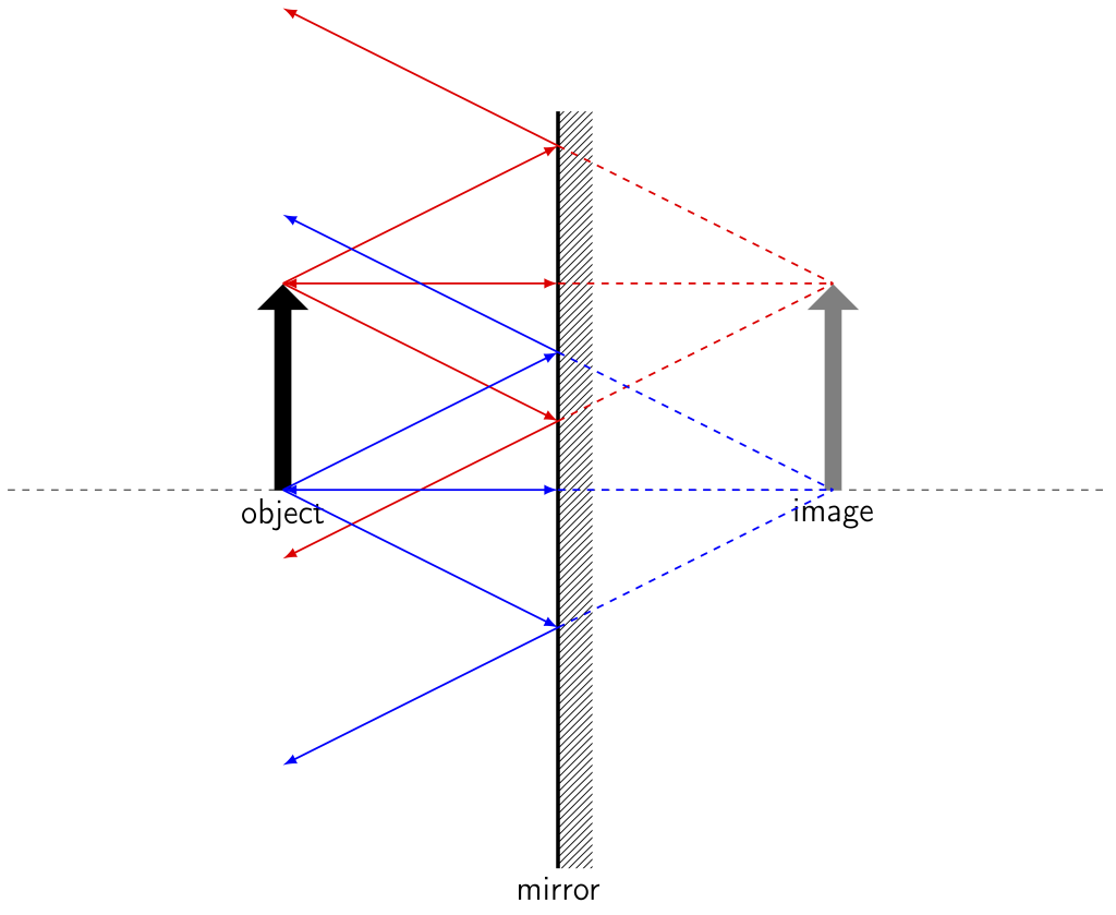
In a planar mirror, the image that appears is behind the mirror: a virtual image. If we trace the reflected rays of an object backward to where they appear to originate, they come together at points behind the mirror, creating a virtual image. Our eyes perceive the diverged light as coming from the virtual image. This virtual image appears upright and has the same size as the object. A ray diagram for a planar mirror is shown in Figure 28.8. The rays colored red in the diagram emanate from the tip of the object and the rays colored blue in the diagram emanate from the tail of the object. Based on their reflection off the mirror, the dashed lines point to where the image appears to have been generated.
A virtual image that is upright and the same size as us corresponds to how we see our own reflections in a planar mirror. Dr. Pasquale took a selfie in a planar mirror; this photograph is shown in Figure 28.9. Note that her image is virtual (appears behind the mirror), upright, and is the same size that she is.

Convex mirror
Mirrors can also be curved. A convex mirror is a mirror that’s curved outward. If parallel rays of light are incident on a convex mirror, they will diverge after reflecting off of the mirror. This is shown with three parallel rays of light in Figure 28.7 (middle). A convex mirror has a focal point. If you were to draw lines tracing the diverged reflected light rays backward, the point where those rays come together is the focal point. Because a convex mirror causes light to diverge, the focal point is behind the mirror.
When we analyze light rays, we see that the object creates a virtual image behind the mirror that’s upright and smaller than the object. A ray diagram for a convex mirror is shown in Figure 28.10.
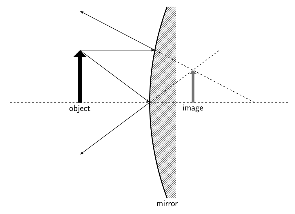
A virtual image that is upright and smaller than we are corresponds to how we see our own reflections in a convex mirror. Dr. Pasquale took a selfie in a convex mirror; this photograph is shown in Figure 28.11. Note that her image is virtual (appears behind the mirror), upright, and is smaller than she is.
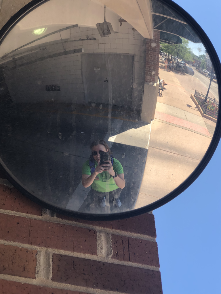
There are many applications of convex mirrors in our lives. Perhaps you’ve seen them in a parking garage or other narrow space, to help you see what may be around a tight corner. A convex mirror seen in a parking garage in downtown Naperville is shown in Figure 28.12.
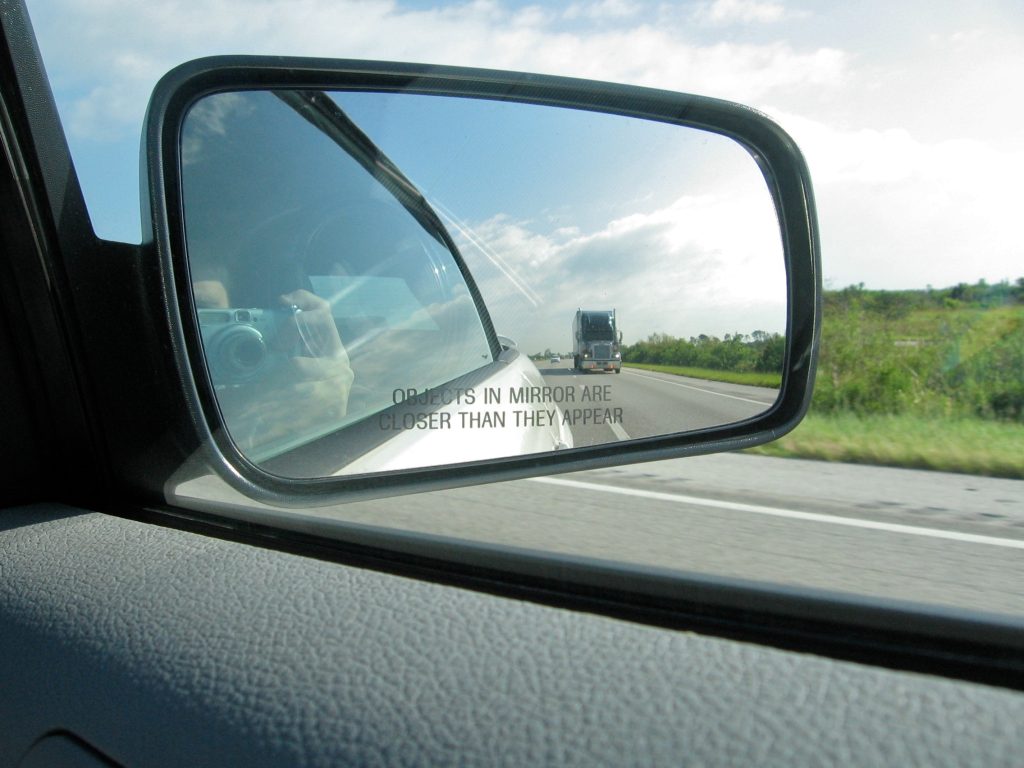
Convex mirrors are also used as the side mirrors in our cars. They show us a slightly smaller version of what’s around us, allowing us to see an expanded view around the sides of our cars. This is also why there’s usually a warning stating, “Objects are closer than they appear,” as seen in Figure 28.13.
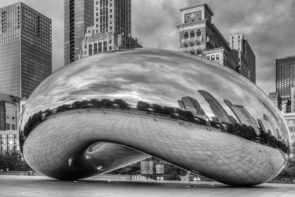
The sculpture Cloud Gate (colloquially known as “The Bean”) in Chicago, Illinois, is composed of convex mirrors on the outer surface. This is shown in Figure 28.14. Note that the images that appear in the sculpture are virtual, upright, and smaller than the objects that created them.
Concave mirror
A concave mirror is a smooth reflective surface that’s curved inward. A concave mirror has a focal point, a place where all parallel rays will converge to a single point. Because a concave mirror causes light to converge after reflecting, the focal point is in front of the mirror. The convergence of three parallel beams of light on a concave mirror is shown in Figure 28.7 (right).
The image that’s created in a concave mirror can be virtual or real depending on where an object is positioned in relation to this focal point.
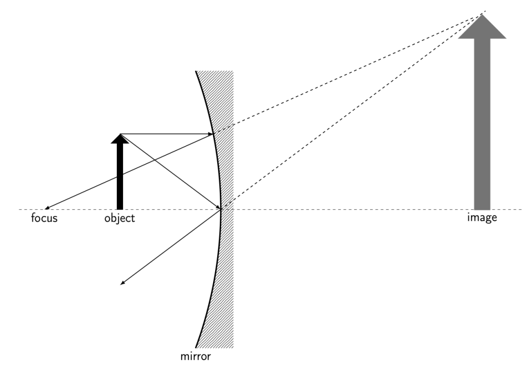
Consider an object that is between the focal point and the mirror. We can draw light rays and use the law of reflection to determine where those light rays will travel after bouncing off of the mirror. Our eyes perceive an image based on where these rays of light converge. In this case, they create a virtual image behind the mirror. The virtual image is upright and much larger than real life. A ray diagram corresponding to this scenario is shown in Figure 28.15.
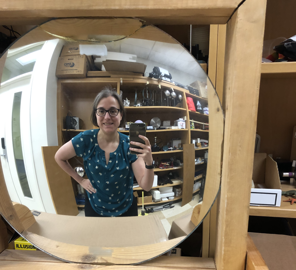
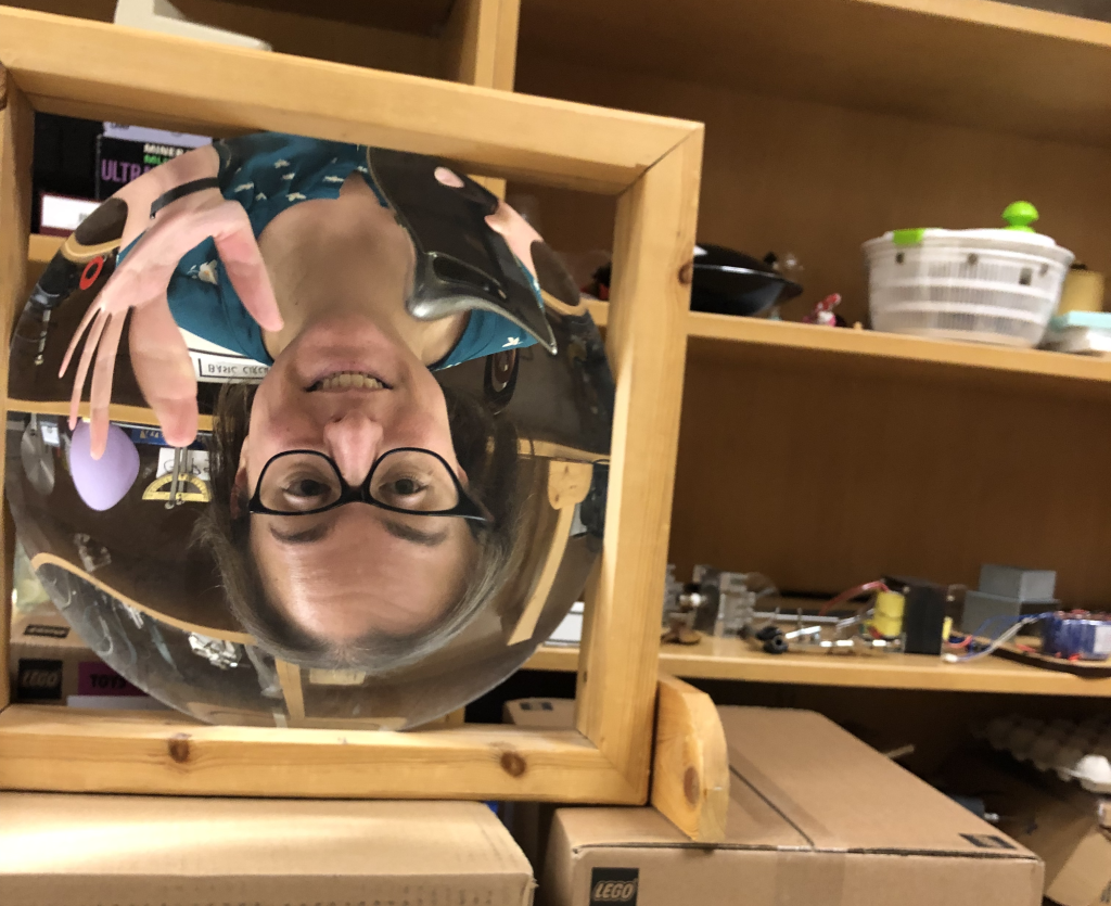
Dr. Pasquale took a selfie while she was positioned between the focal point and the surface of a concave mirror. This photograph is shown in Figure 28.16. Notice that her image is virtual (appears behind the mirror), upright, and is larger than she is.

You may have used a concave mirror in this fashion if you’ve used a makeup or shaving mirror. This greatly magnifies the appearance of your face and makes it easier to apply makeup or to shave.
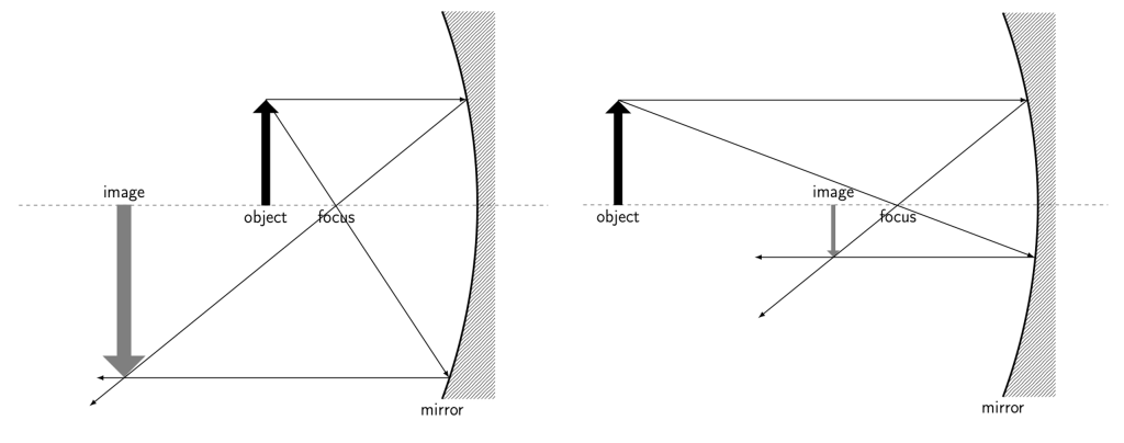
As an object moves past the focal point, the image changes. Now, we can trace each ray of light and see that they converge on the same side of the mirror as the object, causing a real image. Again, the term real image simply means that the image is created on the same side as the object, due to light rays converging rather than diverging. The real image generated in this case is upside down. The image may be larger than, smaller than, or the same size as the object, depending on how far away from the focal point the object is positioned. A ray diagram of a concave mirror with the object past the focal point is shown in Figure 28.17. When the object is close to the focus (Figure 28.17, left) the image is larger than the object. As the object moves farther away from the focus (Figure 28.17, right) the image becomes smaller than the object.
Dr. Pasquale took a selfie while she was positioned past the focal point of a concave mirror. This photograph is shown in Figure 28.18. Notice that her image is real (appears in front of the mirror), upside down, and is larger than she is.
It’s possible you’ve seen this effect if you’ve looked in a funhouse mirror. And if you step far enough away from a makeup or shaving mirror, you’ll notice that you will pass the focal point and go from being upright and magnified to upside down and magnified. If you continue walking backward, your image will go from being magnified to the same size, to smaller than you are.
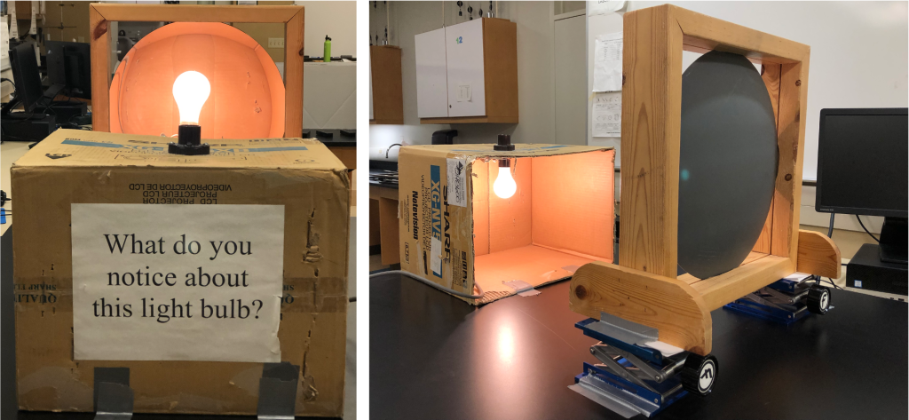
Because a concave mirror generates a real image by focusing light in front of the mirror, that image can be projected onto a screen or seen by others as an optical illusion. For example, in Figure 28.19 (left), a light bulb appears to be screwed into the socket placed on top of a cardboard box. However, when viewed from the side, as in Figure 28.19 (right), the light bulb (object) is actually upside down below the cardboard box. A concave mirror creates the inverted image of the light bulb making it appear right side up on top of the box.
Planar, concave, and convex mirrors are used in reflecting telescopes. A telescope is used to collect light from far away celestial objects and focus it to a point, which is accomplished by using curved mirrors. Typically, a concave mirror is used to collect the incoming light to a point. Either film, a digital recording sensor, or an eyepiece can be placed at that focus to record or view the celestial object. Among many other telescopes that use mirrors is the Hubble Space Telescope.
One-way mirrors
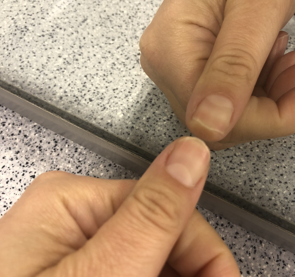
A typical household mirror is simply a very smooth reflective metal (possibly silver and/or aluminum) that’s been highly polished and covered with glass. If you touch the mirror, you’ll notice a gap between your finger and the reflection. (Dr. Pasquale has demonstrated this in Figure 28.20.) This gap exists because of the presence of the glass protecting the polished metal surface.
Perhaps you’ve heard of a one-way mirror. A one-way mirror is simply a piece of glass that separates a dark area and a light area. These surfaces appear to look like a mirror if you’re on the light side of the glass, but they look like a window if you’re on the dark side of the glass. In fact, windows in buildings and homes also appear this way at night when it’s dark outside but interior lighting is used.
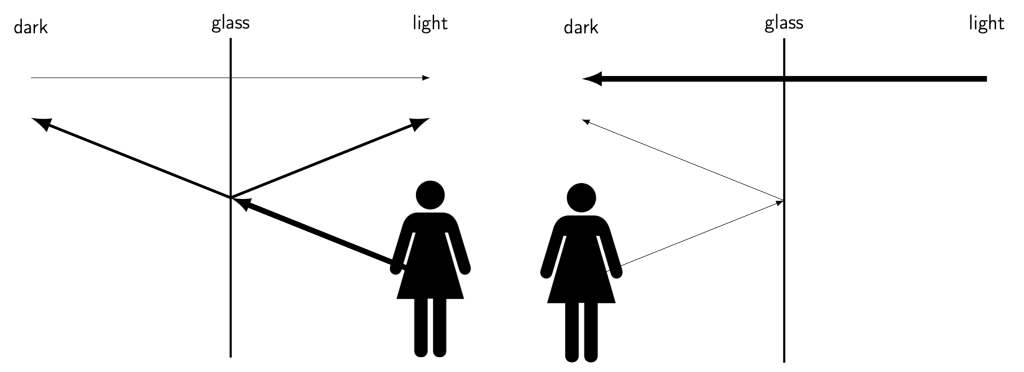
A one-way mirror isn’t really much of a mirror at all. On the light side, we can easily see our reflection because the light from the reflection outweighs the small amount of light passing through from the dark side of the glass (Figure 28.21, left). On the dark side, we simply see the light that transmits through from the bright side (Figure 28.21, right). There is too much transmitted light to enable somebody on the dark side of the glass to see their reflection. Instead, they see whatever is on the other side of the glass.
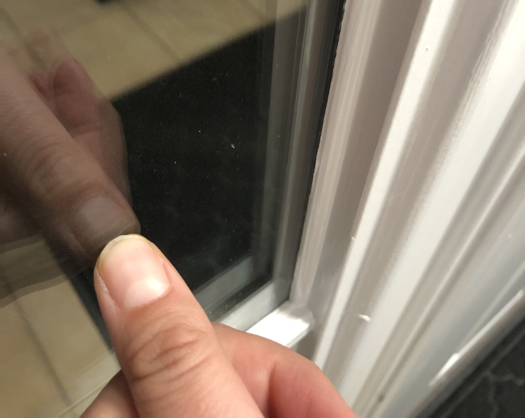
You can identify a one-way mirror by touching the glass. Because there is no metal reflecting surface, you’ll notice there is no gap between your finger and its reflection. This is demonstrated by Dr. Pasquale in Figure 28.22. (Note that this cannot distinguish a one-way mirror from a “normal” mirror that does not have a glass coating over the polished reflective surface.)
Refraction
Refraction is a bending of light that occurs when light travels through different media. Because of the principle of least time, light will bend when it travels from one transparent medium into another. For example, light will bend when it travels from air to a medium such as water or plastic where the speed of light is slower than it is in free space.
The extent to which the speed of light slows down is known as the index of refraction. (Different media can be characterized by their own index of refraction.) Index of refraction has a symbol of the lowercase letter  , and is equal to the ratio of the speed of light in free space and the speed of light in that medium. In equation form,

where  is the speed of light in free space (
 ) and
) and  is the speed of light in that particular medium.
The index of refraction of a medium is an indication of how much light will bend when it enters that medium from free space. Something with a smaller index of refraction will bend light much less than something with a higher index of refraction. For context, water has an index of refraction of 1.3. Diamond has a relatively high index of refraction of 2.4.
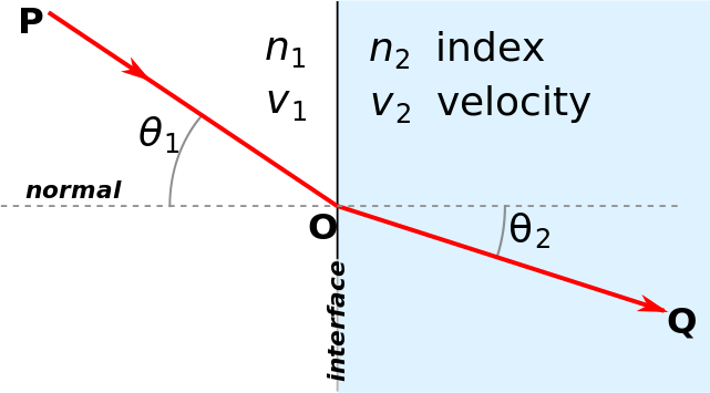
To quantify the bending of light, we look at the normal line at the point where light hits the interface of the two media. (Remember: the normal line is drawn at a 90 degree angle to the medium at that point.) Light enters at an angle of incidence, which is measured with respect to the normal line. This is shown in Figure 28.23, which depicts light traveling from point P to point O in a medium with index of refraction  and speed of
  . The angle of incidence is depicted as
  , measured with respect to the normal line. The light bends at the interface and travels from point O to point Q in a new medium with index of refraction
  and speed of
  . The angle of refraction is depicted as
  , measured with respect to the normal line.
When light travels from a lower to higher index of refraction (for example, from air to glass), the angle of refraction will be smaller than the angle of incidence. When light travels from a higher to a lower index of refraction (for example, from water to air), the angle of refraction will be larger than the angle of incidence.
The exact amount of bending can be explained by Snell’s law of refraction. Note that Snell’s law of refraction contains trigonometry, which you are not expected to be familiar with in this textbook. Therefore, we will only consider Snell’s law qualitatively. In equation form, Snell’s law of refraction states that

where  is the index of refraction of the first medium, is the angle of incidence,
  is the index of refraction of the second medium, and is the angle of refraction.
Because the angle of incidence is measured with respect to the normal line, it can only range between 0 degrees and 90 degrees. This means that as the value of the angle of incidence increases, the sine of the angle of incidence increases as well. Because the product of index of refraction and the sine of the angle is constant on both sides of the equation, if one variable is increased on one side of the equation, the other variable on that side of the equation must decrease to compensate. In other words: as the index of refraction of the second medium increases, the angle of refraction must decrease to keep the product constant (or vice versa).
This bending of light explains some things you may have seen in your everyday life. For example, when a straw is placed in a glass of water, the refraction of light in the water causes the straw to look broken. This is shown with a pen in Figure 28.24. Note that refraction occurs twice: when light travels from air to the glass, and when it travels from the glass to the water.

Refraction is also used to help our eyesight (among other things). This will be explained in more detail later in this chapter.
Dispersion
Although Snell’s law of refraction seems to indicate that the amount of bending that occurs in a material is independent of wavelength, in fact, different wavelengths of light will bend by differing amounts through different media. The index of refraction of a material is not just a single number, but is a function that varies based on the light wavelength. This fact can be used to split light into its constituent colors. This property is known as dispersion.
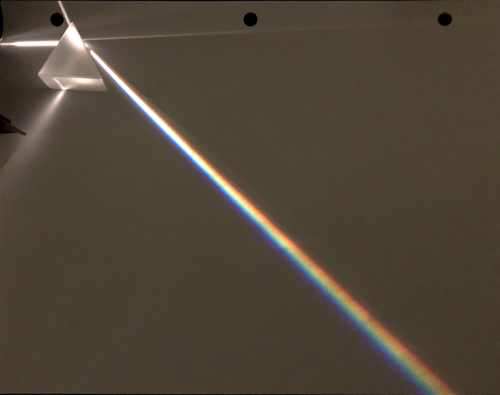
A prism splits white light into a rainbow due to dispersion (recall from the previous chapter of this textbook that white light is a mixture of all colors of light). Each color of light bends different amounts. Red bends the least through glass, and violet the most. This difference in bending is what causes a rainbow to form. A photograph of a prism splitting white light into a rainbow is shown in Figure 28.25.
Dispersion also occurs in raindrops and is the physical cause of rainbows we see in the sky. Rainbows form from a combination of reflection, refraction, and dispersion. In order to see a rainbow in the sky, the Sun needs to be behind you and atmospheric water droplets need to be in front of you. Some of the white light from the Sun refracts into the water droplet and disperses into the familiar spectrum of colors within the droplet. These rays strike the back side of the droplet, where some of the light reflects back into the droplet and continues to disperse. Some of the dispersed light that returns to the front side of the droplet refracts back out toward the observer. Since the index of refraction of water is greater for violet than for red light, the violet emerges on top and the red light emerges at the bottom. In that case, why do the rainbows we see have the red on top of the bow and violet on the bottom? The reverse ordering of the colors arises from the light returning from different droplets.
If red light from droplets reaches your eyes, then the violet light passes over your head. If violet light is reaching your eyes, then the red light is below your head. The rainbow you see is due to dispersed light returning from different droplets. Your eyes intercept the red light from droplets higher in the sky and the violet light from droplets lower in the sky as depicted in Figure 28.26.
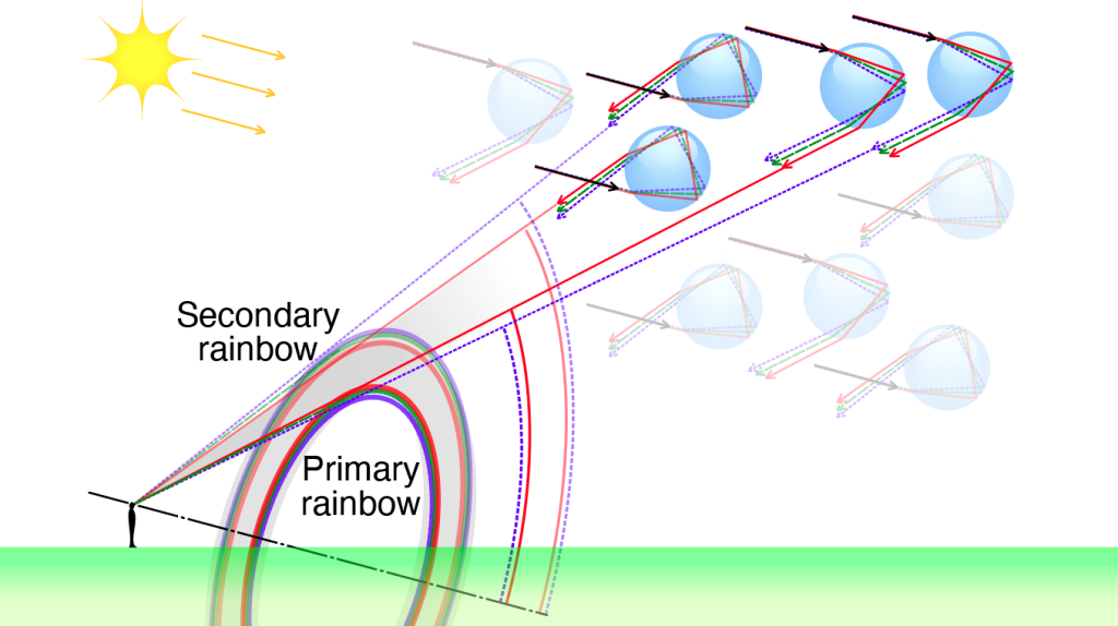
Note that you can often see a secondary rainbow above the primary rainbow. The secondary rainbow comes about from a double reflection within the droplet. Some of the white light from the Sun that enters near the bottom of a droplet can undergo a reflection twice within the droplet and emerge near the top. Note that the ordering of the emerging color spectrum is reversed with red emerging on top and violet emerging on the bottom. This results in the reversed ordering of the spectrum when the double-reflected light from different droplets reaches your eyes. This phenomenon, known as a double rainbow, is shown in Figure 28.27.

Total internal reflection
According to Snell’s law, light that travels from an object with a high index of refraction to a medium with a lower index of refraction will bend the refracted light outward. (The angle of refraction will be larger than the angle of incidence.) At a certain point, known as the critical angle, light that is incident on an interface between a high index of refraction medium and a low index of refraction medium will bend at a 90 degree angle, exactly along the interface. Light that is incident at angles greater than the critical angle will not refract at all, but will instead completely reflect off of the interface. This phenomenon is known as total internal reflection.
Total internal reflection is demonstrated by Dr. Pasquale in the video below. Light enters into a piece of plastic from a light source. At the interface between the plastic and the air, some of the light is bent outward into the air (refracted) and some of the light is reflected off of the interface. As Dr. Pasquale rotates the setup to increase the angle of incidence, eventually, the refracted light bends at a 90 degree angle, and then vanishes. This is the point of total internal reflection.
Total internal reflection is used in fiber optics. Light rays are focused into a long fiber of glass with a laser, and total internal reflection causes those light rays to remain trapped inside of the fiber, allowing them to travel long distances as they carry telecommunications signals from one place to another.
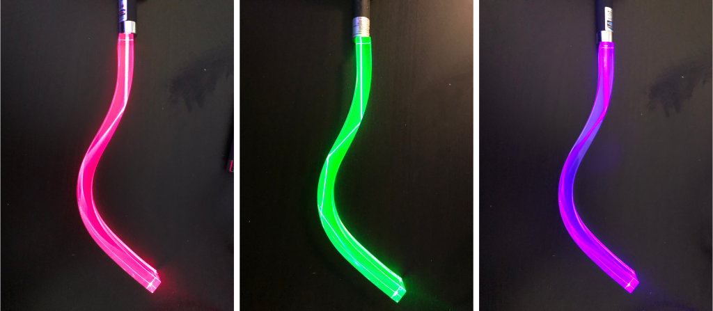
An analogous process is shown in Figure 28.28, where red (left), green (middle), and violet (right) laser pointers were shone into a piece of curved plastic. You can see that when the plastic curves, because it has a higher index of refraction than air, the light from the laser pointers remains inside the plastic due to total internal reflection.
Diamonds are cut with angles such that much of the light that travels into the diamond is trapped inside with total internal reflection, causing them to sparkle and shine.
If you’ve ever been under water and looked upward, total internal reflection is the reason why the surface of water from underneath tends to look shiny, somewhat like a mirror. A photograph of this “mirror-like” property of water’s surface is shown in Figure 28.29. (Note that the fish at the top of the image is a reflection of the fish at the bottom of the image.)

Lenses
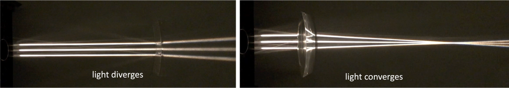
A lens is a piece of transparent material that causes light to bend and either converge or diverge after traveling through it. Parallel rays of light that refract through a lens can diverge or converge after refraction. These two scenarios are shown in Figure 28.30. Each ray of light follows Snell’s law at both interfaces between the air (or other medium) and the lens. The converging or diverging property comes from the shape or curvature of the lens.
Just as mirrors cause reflected light to appear to have been generated from a particular spot, lenses cause refracted light to appear to have been generated from a particular spot. Our eyes perceive the bent light as having come from that spot, known as an image. An image is said to be virtual when the image is on the same side of the lens as the object, and the image is said to be real when the image is on the opposite side of the lens as the object. (This is the opposite of the way we use the terms “virtual” and “real” when discussing mirrors.) This again has to do with whether the lens causes the light rays to diverge or converge beyond the lens. Light rays that converge beyond the lens form a real image that can be projected on a screen. The diverging rays beyond the lens shown in Figure 28.30 (left) do not actually come from the focal point on the left side of the lens. Hence, the image cannot be projected onto a screen and is therefore virtual as described below.
Biconcave lens
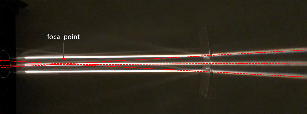
A biconcave lens causes parallel light waves to diverge. Biconcave means that both sides of the lens are curved inward. We can determine that divergence occurs by applying Snell’s law of refraction at each interface between air and the lens. If we trace the diverged light rays backward, we can find a focal point. This is known as a virtual focal point because it’s in front of the lens. The virtual focal point for the lens depicted above in Figure 28.30 (left) is shown below in Figure 28.31.
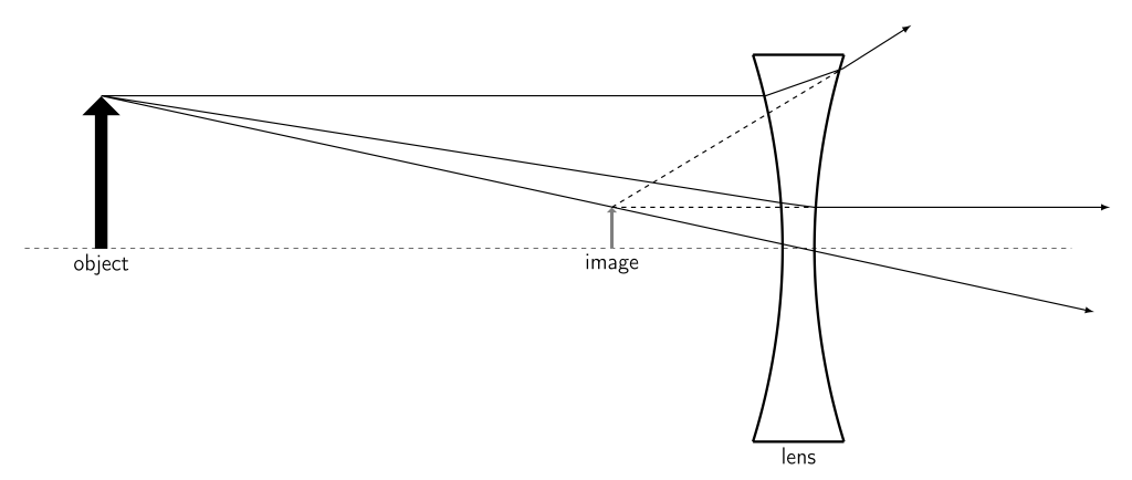
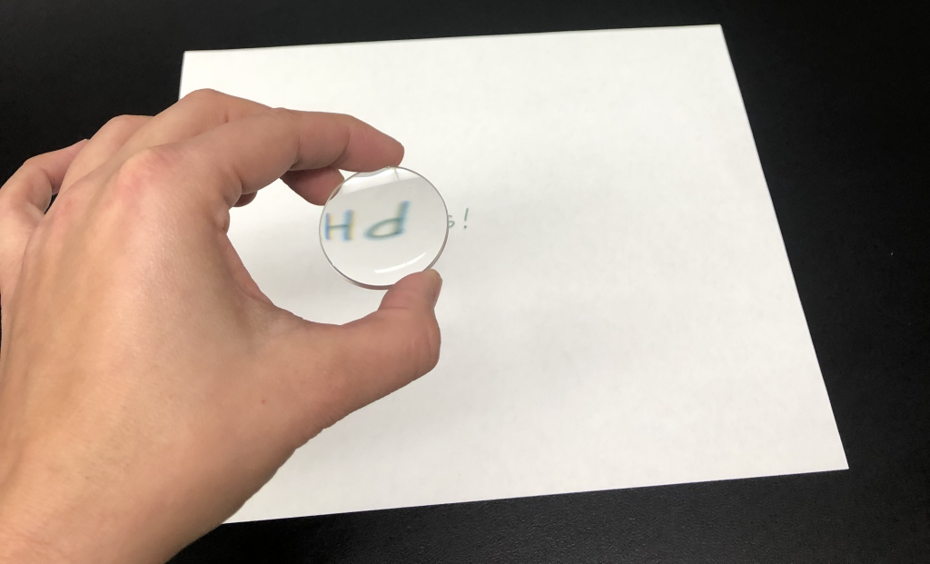
An image viewed through a concave lens will be upright and smaller than the object that creates the image. It is known as a virtual image as it appears on the same side of the lens as the object. A ray diagram for a biconcave lens is shown in Figure 28.32.
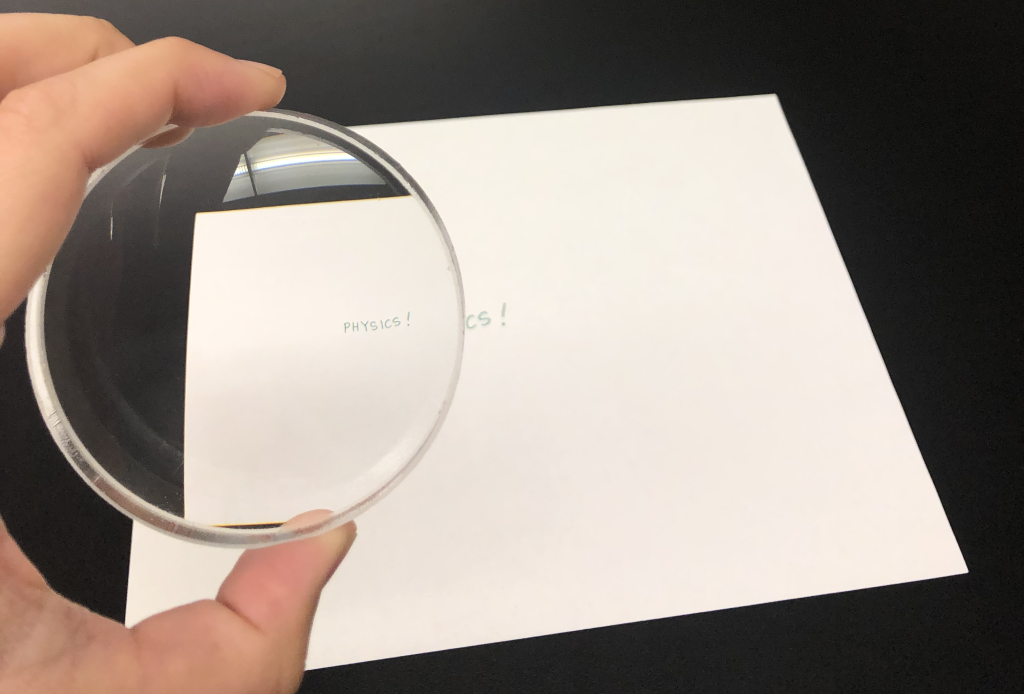
A photograph of the image of the word “PHYSICS!” is seen through a biconcave lens and shown in Figure 28.33. Note that the image is upright and smaller than the object.
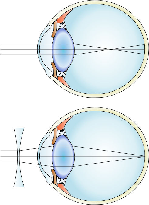
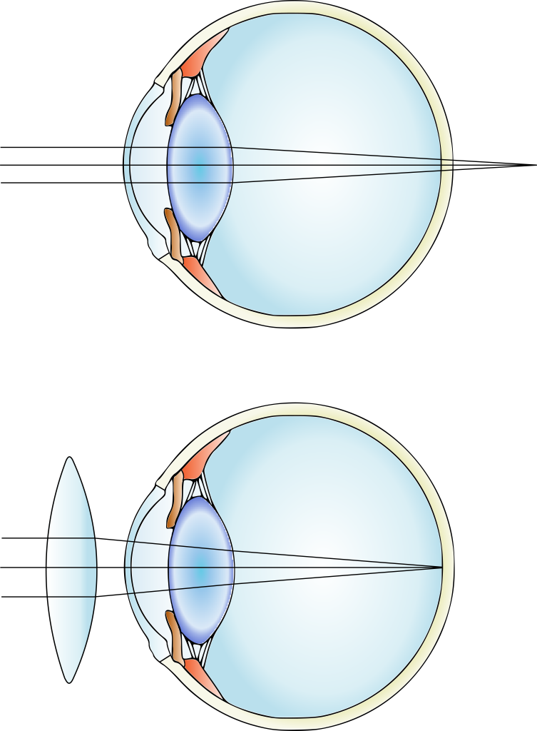
Eyeglasses use refraction of light through glass to focus light on the retina. People who are nearsighted (such as Dr. Pasquale) have eyes that focus light in front of their retina. Eyeglasses are designed to bend the light and cause it to focus on the retina instead. The process to correct nearsightedness uses diverging lenses such as biconcave lenses. The diagram of this process is shown in Figure 28.34.
Biconvex lens
A biconvex lens causes parallel light waves to bend inward, or converge (as shown above in Figure 28.30, right). Biconvex means that both sides of the lens are curved outward. Because light that travels through a biconvex lens converges, the focal point is said to be real. The focal length is the distance between the lens and the focal point. The image that’s created in a biconvex lens has to do with where an object is positioned in relation to this focal point.
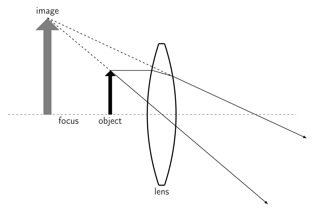
When an object is viewed through a biconvex lens between the focal point and the lens, the image will be virtual, upright, and larger than the object. A ray diagram for a biconvex lens in this scenario is shown in Figure 28.35.
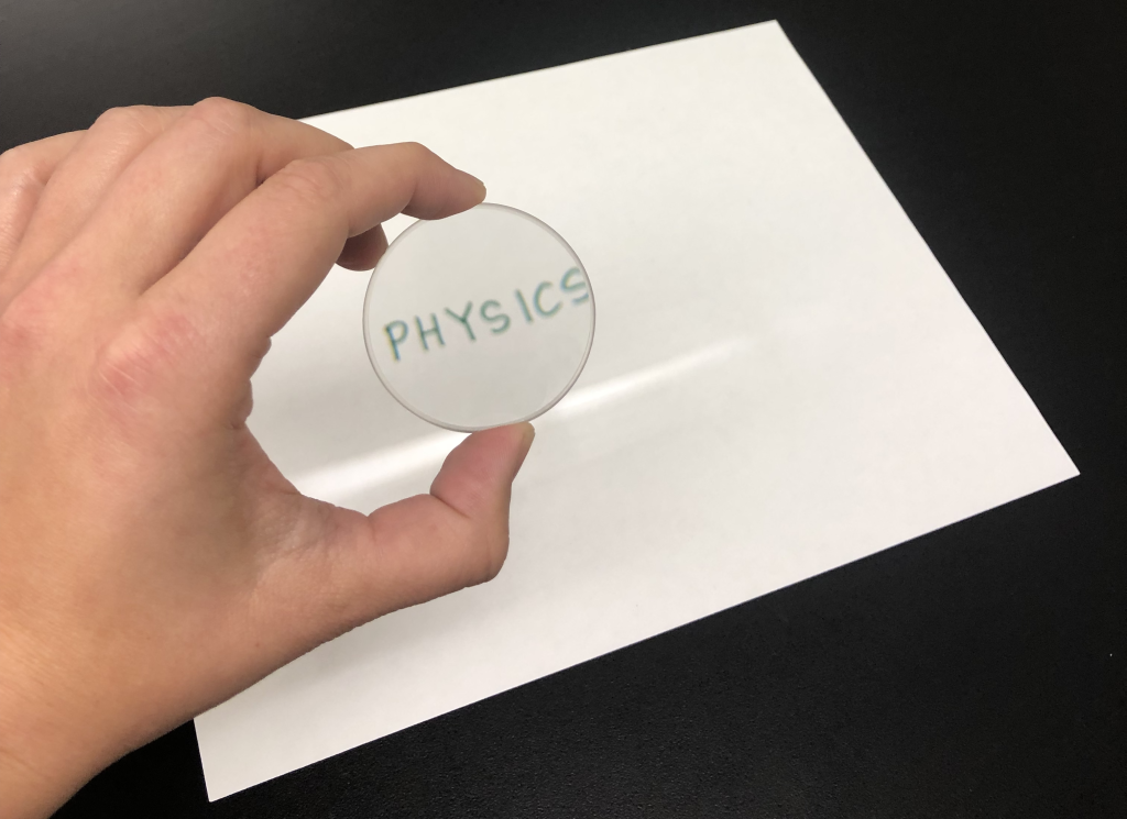
A photograph of the image of the word “PHYSICS!” is seen through a biconvex lens between the focal point and the lens, and shown in Figure 28.36. Note that the image is upright.
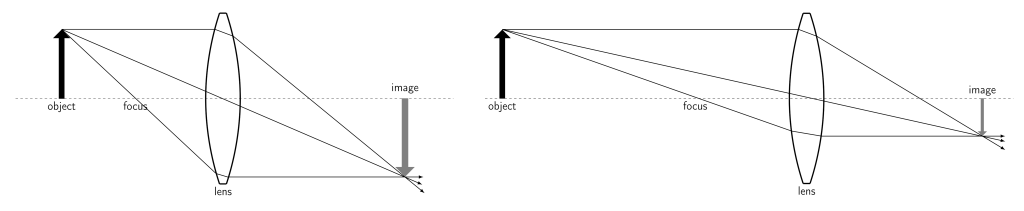
As the object moves away from the focal point, the image changes. When the object moves beyond the focal point, the image becomes real, inverted, and magnified. As the object continues to move farther away, it will eventually become reduced instead of magnified. A ray diagram of a biconvex lens with the object past the focal point is shown in Figure 28.37. When the object is close to the focus (Figure 28.37, left) the image is larger than the object. As the object moves farther away from the focus (Figure 28.37, right) the image becomes smaller than the object.
A photograph of the image of the word “PHYSICS!” is seen through a biconvex lens beyond the focal point and shown in Figure 28.38. Note that the image is inverted and larger than the object.
An application of biconvex lenses is in correcting hyperopia (farsightedness). People who are farsighted have eyes that focus light behind their retina. For example, Dr. Fazzini needs to wear reading glasses or “readers” that use a converging lens (such as a biconvex lens) to correct hyperopia by focusing light onto the retina. The diagram of this process is shown in Figure 28.39.
Other lens applications
Because lenses have the ability to reduce and enlarge the size of objects when creating images, they are widely used in many optical applications where small or distant objects need to be enlarged.
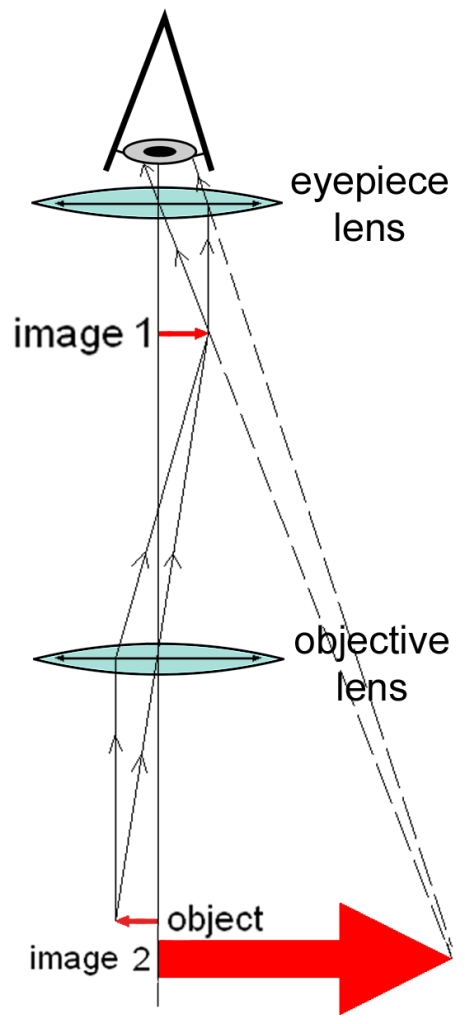
Optical microscopes use visible light to enlarge an object so it can be seen with more detail. A compound microscope uses two lenses (an eyepiece lens and an objective lens) to create an enlarged, upright image, as shown in Figure 28.40. Some compound microscopes can project the image onto a sensor for recording as a digital image.
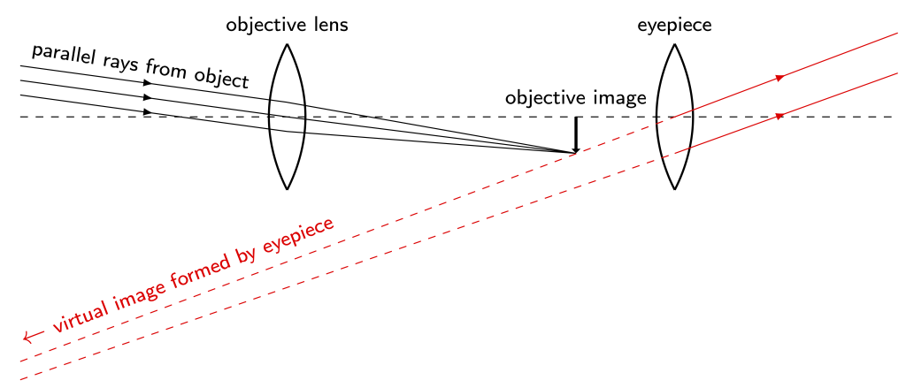
Refracting telescopes make use of lenses to make images of distant objects in the night sky. A ray diagram for a simple refracting telescope is shown in Figure 28.41. Parallel rays of light from a distant celestial object are focused to a point by an objective lens, creating a real image in between the objective and eyepiece lenses. This image becomes the object for the eyepiece lens, which creates the magnified virtual image viewed by the user of the telescope.
Refracting telescopes are ultimately limited in size by the ability to manufacture large lenses. (In addition, the need to mount lenses on their edges so as not to obstruct the field of view can cause gravitational issues with large lenses.) They also suffer from chromatic aberration, which is a type of lens defect described below. Refracting telescopes have been mostly replaced by reflecting telescopes, which use a collection of mirrors instead of lenses to create an image of distant objects.
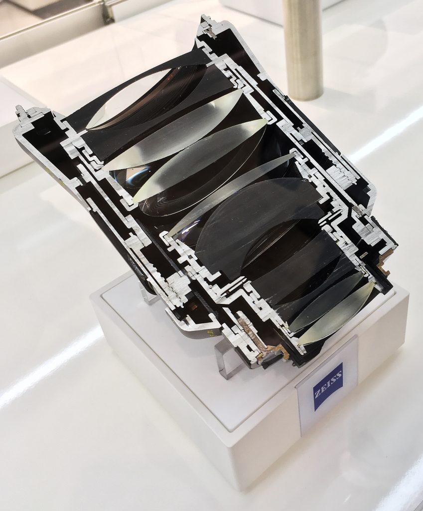
Cameras use lenses and mirrors to focus light onto film (or other light-sensitive material) or a digital sensor to create an image. There are many types of camera lenses, each of which are typically composed of multiple lenses. The camera lens shown in Figure 28.42 has been cut in half to demonstrate this property. Whether a camera lens acts as a telephoto (zoom) lens or a wide-angle lens (or something else) has to do with the lenses that are used.
Optical aberrations
While lenses and mirrors are built to create images, there can be issues with lenses and mirrors due to their composition and construction. A distortion or aberration occurs when light is not focused at a single point. Instead, light rays are spread out around the focal point.
Spherical aberration
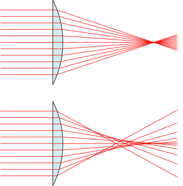
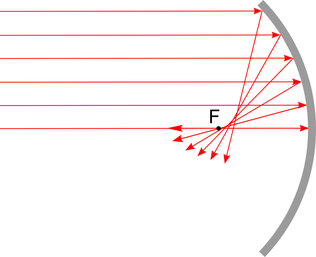
Both lenses and mirrors can both suffer a type of distortion known as spherical aberration. To obtain a single focal point, a parabolic mirror or lens shape is required. However, a spherical shape is much easier to manufacture. This aberration is not prevalent for light rays that are incident close to the center of the lens (or mirror). However, when light is incident far from the center of the lens or mirror, the difference in focal point will be quite pronounced.
A parabolic lens without spherical aberration is shown in Figure 28.43 (top), while a spherical lens that does suffer from spherical aberration is shown in Figure 28.43 (bottom).
A mirror with spherical aberration is shown in Figure 28.44.
Chromatic aberration
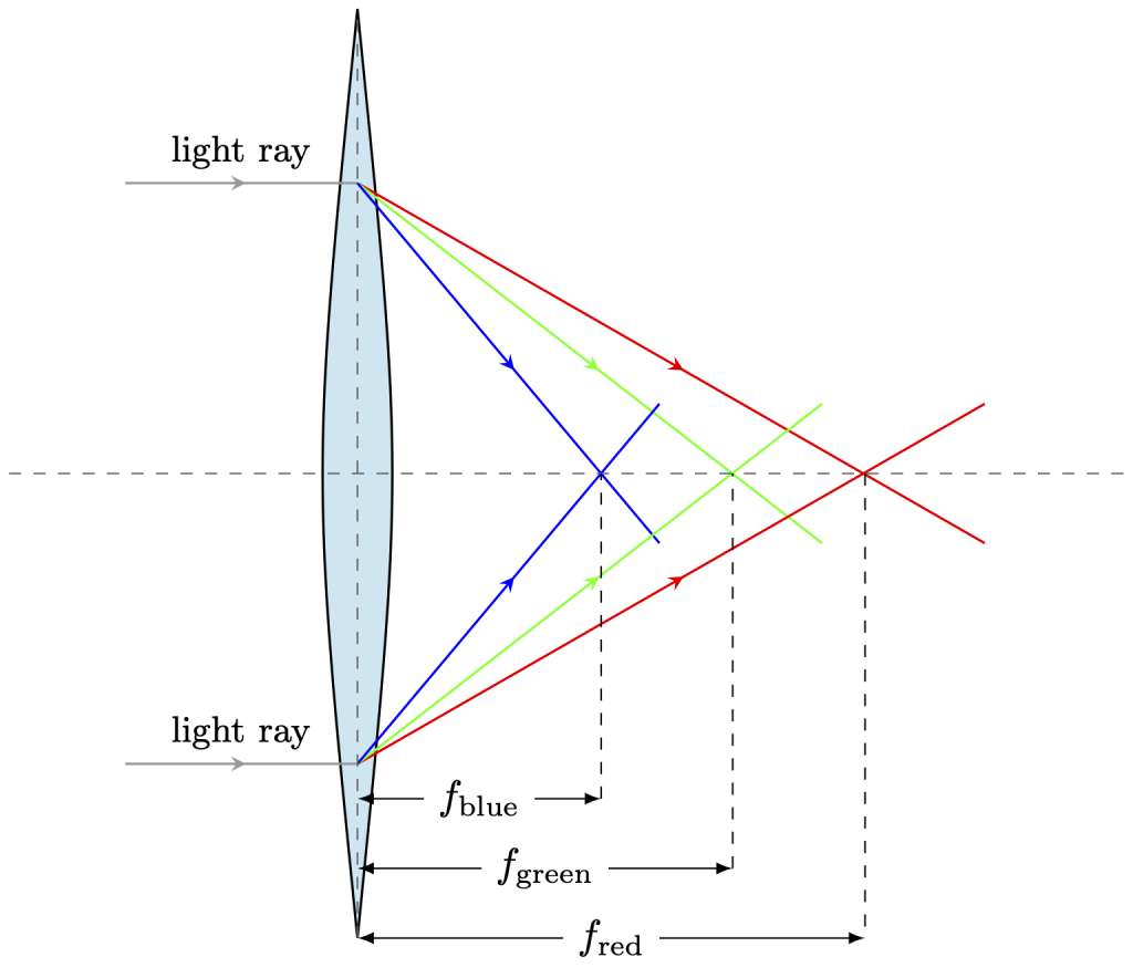
Chromatic aberration occurs when different colors of light focus at different focal points. This is due to dispersion. Through glass or plastic lenses, red light will bend less than blue light, all other things being equal. An exaggerated depiction of chromatic aberration is shown in Figure 28.45. Lenses suffer from chromatic aberration regardless of their shape. However, mirrors do not because the law of reflection holds regardless of the wavelength of the light.
Further reading
- Yerkes Observatory – The Yerkes Observatory in Lake Geneva, Wisconsin, contains two telescopes: one refracting and one reflecting telescope. The refracting telescope at Yerkes was the largest in the world as of the time of its dedication in 1897. Since then, many notable scientists have made use of the telescope to conduct scientific research.
Practice questions
Hands-on experiments
- Shine a flashlight onto a mirror at different angles. Observe the angle of incidence and the angle of reflection (measured with respect to the normal line). Use a ruler to measure and compare these angles.
- Fill a clear glass with water. Place a pencil in the glass and observe how it appears bent or displaced. Does the bent appearance change based on the angle from which you observe the glass? (Look from above, below, and from the sides of the glass.)
- Place a coin at the bottom of a clear glass. Observe the coin from the side of the glass and then from above the water level. How does refraction change where the coin appears to be located?
The principle of least time describes how light travels. Light does not necessarily take the shortest distance between two points. Instead, it will travel whatever path takes the least amount of time.
Path describes the total distance that an object travels as it moves from one point to another, measured along its trajectory. It is a scalar quantity. (symbols: d, x [for horizontal path], y [for vertical path], unit: m)
Velocity is the vector quantity that describes the rate at which an object changes its position. Velocity is equal to displacement divided by time. (symbol: v, unit: m/s)
Speed is the scalar quantity that describes the rate at which an object changes its position. Speed is equal to position divided by time. (symbols: s, |v|, unit: m/s)
Reflection occurs when a wave bounces off of a surface and subsequently changes its direction.
A wave is a periodic oscillation that transfers energy from one place to another.
Absorption of light occurs when light waves completely transfer their energy to a medium as they attempt to pass through it. The light is therefore blocked from transmitting through the medium.
An object is opaque if it does not allow any light to transmit through it.
The law of reflection states that the angle of reflection of a wave is equal to the angle of incidence of that wave.
Refraction occurs when a wave changes speed (and therefore bends) at an interface between two different media.
An object is transparent if it allows visible light to pass through without getting scattered or absorbed.
The wavelength of a wave describes the shortest distance between two identical repeating points on a wave. (symbol: λ, unit: m)
Total internal reflection describes the phenomenon that occurs when light travels from an object with a high index of refraction to an object with lower index of refraction at an angle greater than the so-called critical angle. Light that is incident at angles greater than the critical angle will not refract at all, but will instead completely reflect off of the interface.
An optical aberration occurs when light (incident on a mirror or traveling through a lens) is not focused at a single point. Instead, light rays are spread out around the focal point.

#/media/File:Fényvisszaverődés.jpg)