26. Light
Summary
Electromagnetism
As we’ve learned in the previous two chapters of this textbook, electricity can generate magnetism and magnetism can generate electricity. As fields, a changing magnetic field can generate an electric field, and a changing electric field can generate a magnetic field. This process does not require the presence of a magnet or an electronic circuit. An electromagnetic wave is a transverse wave composed of both an oscillating electric field and an oscillating magnetic field, both at right angles to each other. Those oscillating electromagnetic fields propagate through space in a direction that is perpendicular to both the electric and magnetic fields. This is depicted in Figure 26.1. Note that because the direction of oscillation of the fields is perpendicular to the direction of wave motion, electromagnetic waves are transverse waves.
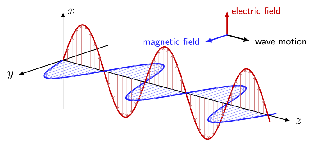
Electric and magnetic fields have been animated and are shown in the video below. This animation demonstrates the motion of each field, and the motion of the wave itself.
The speed of light, represented by the lowercase letter  , is
, is

That is, 300 million meters per second! In the early 1860s, James Clerk Maxwell discovered that the speed of electromagnetic waves is equal to the speed of light, leading him to conclude that light is simply a type of electromagnetic radiation. Maxwell brought together four equations to unify the concepts of classical electricity and magnetism. While these equations (which require vector calculus to solve) are outside the scope of this textbook, it is enough to note that Maxwell’s equations are used today by scientists, engineers, and students all around the world to study electromagnetism.
In the early twentieth century, Albert Einstein postulated that the speed of light is constant, and acts as something like a universal speed limit. As far as we know, nothing can travel faster than the speed of light. While electromagnetic waves can travel at the speed of light, this speed serves as an asymptotic upper limit to objects with mass.
Electromagnetic waves are capable of traveling through the vacuum of space. This makes them very different from waves such as sound and water waves that require a medium to travel through. In fact, light travels through the vacuum of space between stars and our planet. Notably, the Sun produces most of the electromagnetic radiation we experience here on Earth.
We can use the speed of light to calculate how long it takes light waves to travel between the Sun and the Earth. Because the velocity is constant throughout the trip, we can use the equation  to solve for time:
  . The distance between the Earth and Sun is approximately 150 billion meters. Therefore, the amount of time it takes light to travel this distance is

If the Sun were to somehow disappear, we wouldn’t be aware of that fact until 8.3 minutes later when the light stopped reaching the Earth’s surface.
SI prefixes
Our discussion of electromagnetic waves will require us to discuss quantities that are both extremely small and extremely large. Instead of using scientific notation to deal with these quantities, we can instead use prefixes. SI prefixes have been standardized for use with the International System of Units (SI). These prefixes can be used with any type of SI unit: meter, volt, second, gram, and so on. The SI prefixes that are used in this chapter are defined in Appendix B.
The electromagnetic spectrum
There are many categories of waves in the electromagnetic spectrum. Each of these waves can be defined in different categories, and each type of wave has different properties. The electromagnetic spectrum defines each type of wave based on its frequency or wavelength. Because the speed of electromagnetic waves is a constant, wavelength and frequency are inversely related to each other. If frequency is known, the wavelength of an electromagnetic wave is

If wavelength is known, the frequency of an electromagnetic wave is

While we will discuss the equation used to define the energy of an electromagnetic wave later in this textbook, for now it is sufficient to state that the energy of an electromagnetic wave is proportional to frequency and inversely proportional to wavelength. The different types of electromagnetic waves, arranged from smallest to largest wavelength, are listed in Figure 26.2.
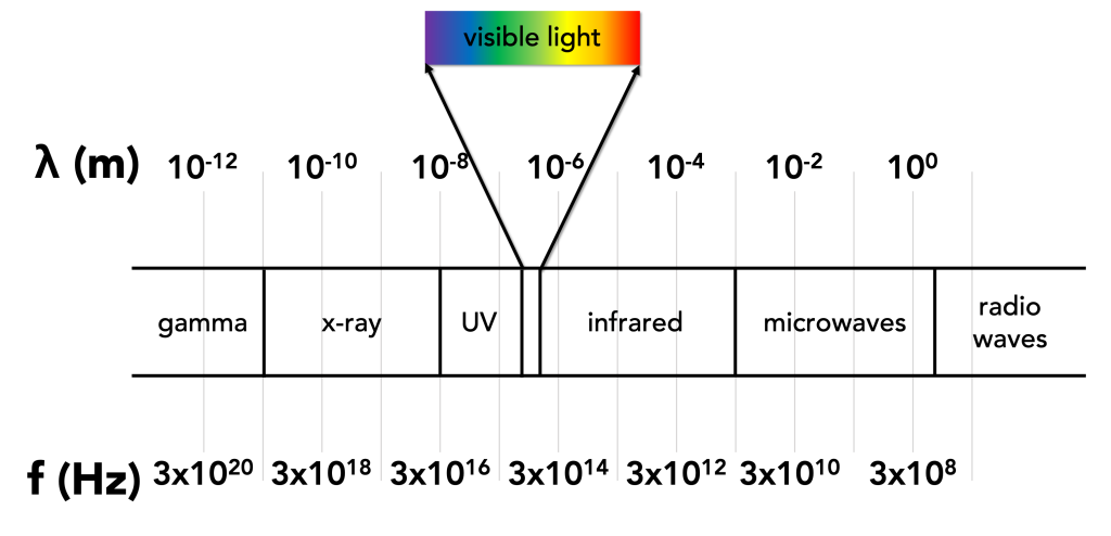
At the lowest energy, lowest frequency, longest wavelength end of the spectrum are radio waves. These waves have wavelengths greater than 3 m, which correspond to frequencies less than 100 MHz.
Next along the spectrum are microwaves. Microwaves have wavelengths between 3 m and 1 mm, and frequencies ranging from 100 MHz to 300 GHz.
Infrared radiation, or IR, has wavelengths between 1 mm and 700 nm. The frequencies range from 300 GHz to 430 THz.
Visible light is the light we can see with our naked eyes. Visible light is a very tiny portion of the electromagnetic spectrum, encompassing wavelengths from 700 nm to 400 nm. The longest wavelength of visible light corresponds to red, and the shortest wavelength of visible light corresponds to violet. The frequencies of visible light span from 430 THz to 750 THz.
The next three categories of waves along the electromagnetic spectrum are high energy, collectively referred to as ionizing radiation. Ultraviolet, or UV, radiation has wavelengths between 400 nm and 10 nm. These correspond to frequencies between 750 THz and 30 PHz.
Next are x-rays. X-rays have wavelengths between 10 nm and 10 pm, and frequencies between 30 PHz and 30 EHz.
Any electromagnetic radiation with wavelengths less than 10 pm and frequencies above 30 EHz are known as gamma radiation. These are the highest energy waves on the electromagnetic spectrum.
Radio waves
Radio waves, as mentioned, comprise the lowest-energy region of the electromagnetic spectrum. Contrary to what the name implies, the waves we tune into on a radio to listen to music or talk radio are not the only kinds of waves that fall under the category of radio waves.
Radio waves are used predominantly for communications applications. It may be useful to review why radio waves (a type of electromagnetic wave) are used to transmit information instead of sound waves. As previously discussed in this textbook, sound waves are longitudinal pressure waves. They require some type of medium through which to travel (and cannot travel through space). This means that sound waves cannot be used for any kind of communication that routes through satellites (for example), which would require travel through the vacuum of space. In addition, sound waves don’t travel very far before they become inaudible. To hear the sound of somebody’s voice over long distances, another method for transmitting that sound is required.
To that end, a sound wave can be encoded onto a radio wave and transmitted by means of some electric circuitry and an antenna. Radio waves are part of the electromagnetic spectrum, travel at the speed of light, and can easily transmit through the Earth’s atmosphere over much longer distances than sound waves. These radio waves are received by something like a radio or walkie-talkie and decoded back into vibrations through a speaker into sound waves.
The radio wave portion of the electromagnetic spectrum is used for many applications. This is because long-wavelength light can travel over very long distances. Some radio waves can reflect off of the Earth’s ionosphere and travel nearly around the globe. Many radio waves can travel through clouds and storms, which means that their transmission will not be affected by weather. The longest wavelengths of radio waves are only limited by the difficulty in generating these waves, which would require extremely large antennas.
The applications of radio waves include telephone signals; military, aircraft, and maritime communication; aircraft navigation; WWVB and other similar time signals; CB and amateur radio; TV broadcasts; and AM/FM radio.
AM and FM Radio
AM and FM refer to the two methods of sending radio waves to a radio receiver. These are amplitude modulation (AM) and frequency modulation (FM). These two modulation methods describe how a sound wave can be converted into a radio wave.
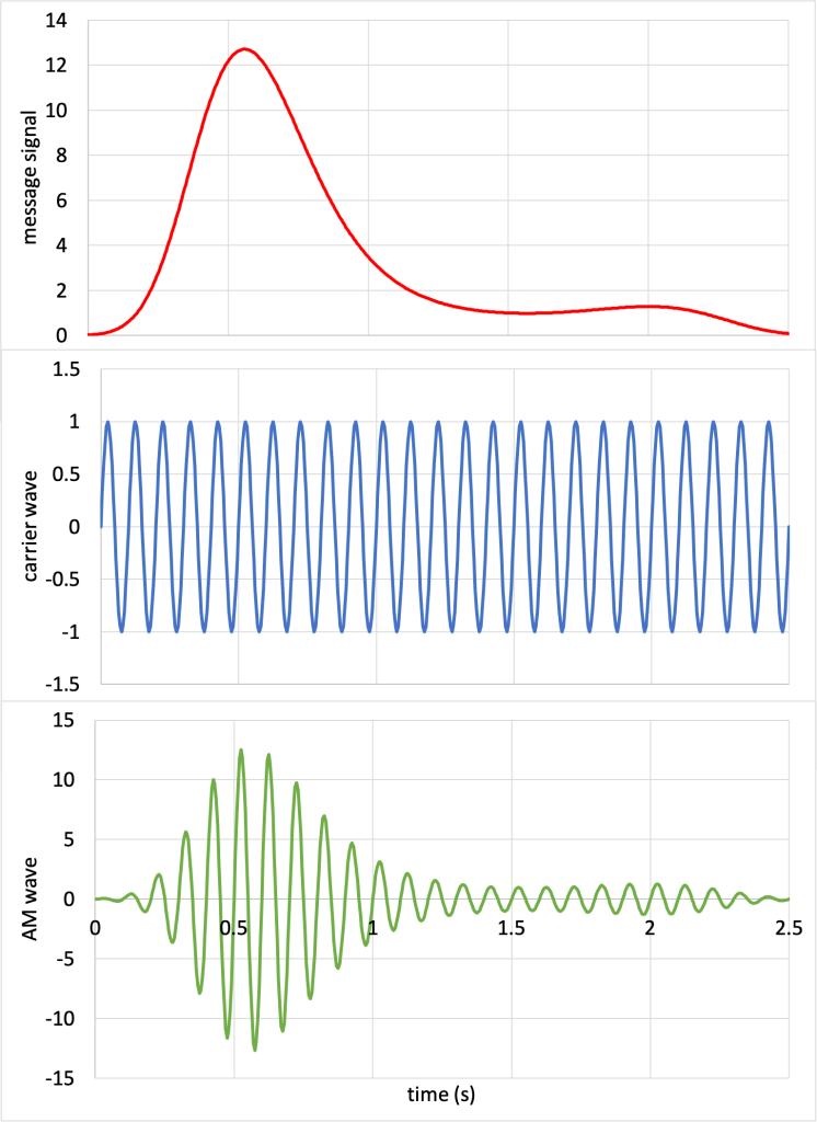
In amplitude modulation (AM), the amplitude of the radio wave (known as the carrier wave) is modified to reflect changes in the sound wave (message signal). This is depicted in Figure 26.3. (Download this data [XLSX, 32 kB]) The amplitude of the carrier wave is multiplied by the amplitude of the message signal, creating an amplitude modulated wave.
The frequencies of AM radio stations in the US vary from 540 kHz to 1700 kHz. AM radio, while popular in the early twentieth century, is now used very infrequently, and may be considered by some to be obsolete. Many AM radio stations consist of talk or sports radio. Because of the long wavelengths of AM radio, the signals travel very far. However, because the wavelengths are physically large, they do not transmit well through small spaces like tunnels. AM radio reception may therefore become blocked when driving through tunnels, underpasses, or possibly even parking garages.
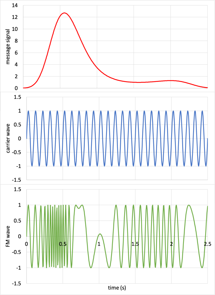
In frequency modulation (FM), the frequency of the radio wave (known as the carrier wave) is modified to reflect changes in the sound wave (message signal). This is depicted in Figure 26.4. (Download this data [XLSX, 33 kB]) The frequency of the carrier wave is modified by the amplitude of the message signal, creating a frequency modulated wave.
The frequencies of FM radio stations in the US vary from 88.1 MHz to 107.9 MHz. FM radio is much more popular than AM radio as it is less susceptible to noise and has much higher sound quality than AM radio. However, due to the shorter wavelengths, FM radio signals cannot travel as far.
Infrared
As we learned in a previous chapter of this textbook, one of the mechanisms of heat transfer is via electromagnetic radiation. Most “cool” objects such as humans, plants, and animals emit heat in the infrared (IR) region of the electromagnetic spectrum. Therefore, the infrared region of the electromagnetic spectrum is extremely important in any area of science and technology that requires us to study heat.
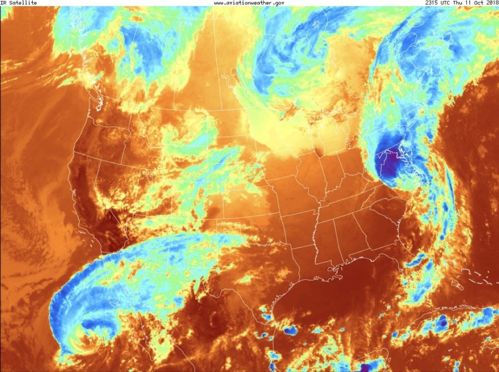
Thermal cameras have a sensor that collects infrared radiation rather than visible light. This allows us to use IR for night vision, thermal imaging, and many other applications. For example, satellite imagery of cloud coverage is used for weather observations that aid in forecasting. After sunset and before sunrise, visible satellite images cannot record any meaningful weather data. However, IR satellites can take images corresponding to the heat reflected from the planet’s surface, which correlates to cloud coverage. (As long as there is no extensive snow cover on the ground, the Earth’s surface tends to have a much higher temperature than the temperature of clouds. Therefore, the cool areas in an IR photograph typically correspond to areas of cloud coverage.)
Figure 26.5 shows a visual satellite image taken just after sunset in Illinois on October 11, 2018. The entire east coast and most of the Midwest is dark, due to the fact that there was no light present to create an image. While there is evidence of a large storm (Tropical Storm Sergio) near the Baja California Peninsula, and sporadic cloud coverage over the western portion of the United States, no other evidence of storms is present.

An infrared satellite image taken at the same time (shown in Figure 26.6) shows a very different picture. While Tropical Storm Sergio is visible in both images, only the IR satellite image contains evidence of Hurricane Michael that had recently made landfall on the east coast.
Microwaves
Microwaves travel line-of-sight distances. Unlike radio waves, they cannot bounce off the ionosphere or travel along the curvature of the Earth. For this reason, microwaves are used in applications where signals only need to travel over short distances. Some, but not all, microwaves can transmit through buildings, but again, only over short distances.
Much of our modern life is transmitted over microwaves: Wi-Fi, Bluetooth, cellular, and GPS and other satellite signals all are part of the microwave region of the electromagnetic spectrum. In addition, things such as garage door openers, collision detectors in cars, and radar use microwaves.
Perhaps when you heard the word microwave, you thought about cooking food. In fact, microwave ovens do use microwaves to cook food. At just the right frequency, microwaves can cause the water and fat molecules in food to heat up. Microwave ovens emit microwave radiation at a 2.45 GHz frequency, usually with power levels between 600 W and 1200 W. Most microwave ovens contain a sticker inside the door that shows the frequency of operation and power level. Dr. Pasquale’s microwave oven emits at 2.45 GHz and has a power rating of 950 W, as seen in Figure 26.7.

It is interesting to note that most of our Bluetooth and Wi-Fi communications also occur right around the 2.4-2.5 GHz frequency range. Our mobile devices communicate using complex protocols that ensure that one signal does not get confused for another. A laptop’s Wi-Fi receiver will not get confused if there is a cell phone nearby receiving a phone call or text message. Also, the reason that a microwave oven is dangerous enough to require metal shielding, and cell phones and wireless routers are not, is due to the power rating. A microwave oven uses microwave radiation at power levels about one thousand times stronger than those used by our modern telecommunication devices.
Ionizing radiation
Electromagnetic radiation with frequencies greater than that of visible light (short-wavelength ultraviolet, x-rays, and gamma rays) is known as ionizing radiation. That’s because the energy of these waves is so great that it can ionize atoms. This can be very dangerous for humans, plants, and animals, as it can cause damage to our DNA and other tissues.
Ultraviolet
Ultraviolet (UV) radiation is emitted by the Sun. Some of this UV transmits through the Earth’s atmosphere, and is the reason why our skin becomes darker with sun exposure. Sunscreen can help block the damage caused by UV light. Higher frequencies of UV are blocked by the Earth’s ozone layer and do not reach the surface of the planet.
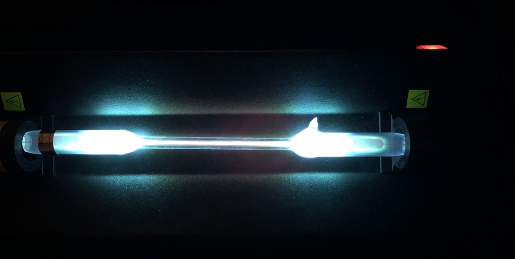
While ultraviolet radiation can be damaging to us, that doesn’t mean it isn’t useful. Mercury vapor lights (such as the one shown in Figure 26.8) generate UV, which then is converted by a phosphor to visible light. This is how fluorescent lamps work, as will be discussed later in this textbook. The integrated circuits comprising your computer processor are fabricated in clean rooms using a photolithography process that uses UV rays to pattern the transistors in the processor hardware. UV is also used in medical imaging, sterilization, bug zappers, and curing lamps.
X-rays
X-rays were discovered in 1895 by physicist Wilhelm Röntgen, who discovered rays that had different properties than other known rays at the time. The letter “x” in x-ray signified that the rays were unknown and novel at the time. Röntgen made an image of his wife’s hand with x-rays, creating the first radiograph and demonstrating the medical use of these new types of rays.
Unfortunately, the medical hazards of x-rays were not discovered until the late 19th and early 20th centuries; precautions that we use today in medical radiography were not practiced early after the discovery of x-rays, and people suffered burns and even cancer as a result of being exposed to high doses of x-rays for long periods of time.
Since their discovery, x-rays have been used widely in medical imaging. Their ability to permeate through soft tissue and be blocked by our bones makes imaging with x-rays an extremely helpful diagnostic tool. An x-ray image of a broken ankle is shown in Figure 26.9.

Other medical uses of x-rays include computed tomography (CT) scanning (creating multiple x-ray images to obtain cross-sectional images of anatomy), fluoroscopy (using x-rays to determine the real-time location of anatomy and possibly even surgical implements during a medical procedure), and radiotherapy (purposefully using the ionizing properties of x-rays to treat cancers).
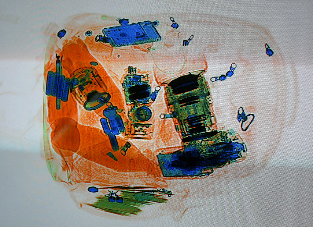
X-rays are also used in airport security to check carry-on bags for the presence of explosives, firearms, or other prohibited items. A radiograph of a backpack is shown in Figure 26.10.
In addition to the medical uses of x-rays, they are also used in many fields of scientific and engineering research. For example, x-rays can be used to determine the crystalline structure of materials. This was how the double helix shape of DNA was determined in the middle of the 20th century by Rosalind Franklin. The Advanced Photon Source at Argonne National Laboratory creates x-rays for use in scientific research.
Gamma rays
Gamma rays reside at the highest energy end of the electromagnetic spectrum. Gamma rays are produced by radioactive decay, a process we’ll discuss later in this textbook. Gamma radiation is extremely hazardous to humans, as it can cause damage to our internal organs and bone marrow. Gamma radiation, while dangerous, does have its applications. Its ability to travel through many objects makes it useful for scanning objects in container trucks at border checkpoints and irradiating objects from harmful bacteria; gamma rays also have limited use in nuclear medicine.
Light waves
Light waves have lots of interesting properties. In fact, we’ll learn later in this textbook that light is not just a wave. There is a lot more to it!
There are many things that can happen to electromagnetic waves as they travel between two points. Reflection and refraction have to do with bouncing and bending, which will be discussed in a later chapter of this textbook. If you have ever looked in a mirror, then you have experienced the reflection of light waves.
Light can also be transmitted and absorbed. When you look out a window, visible light transmits through and you can see what’s going on outside. If, however, you look at a wall, visible light does not transmit through, and you cannot see through the wall. A combination of reflection and absorption on the other side of the wall prevents the light from getting through to your side. We’ll discuss how transmission and absorption play a role in the colors of objects in the next chapter of this textbook.
Whether or not objects allow light waves to pass through gives them different properties. An object is opaque if it does not allow any light to transmit through it. In Figure 26.11 (left), Dr. Pasquale holds a piece of opaque cardboard up between her face and the camera. Because no visible light can transmit through the piece of cardboard, her face is not visible in the photograph. (In addition, when the photo was taken, she could not see the camera either.)

An object that allows light to pass through, but scatters the light in the process, is known as translucent. This means the image becomes blurry or otherwise hard to make out entirely. In Figure 26.11 (middle), Dr. Pasquale holds a sheet of translucent plastic between her hand and the camera. You can vaguely see her hand behind the sheet, but it is blurry and lacks detail. In general, viewing something behind a translucent object means that you typically can see an object on the other side, but may not be able to give any detail about it.
An object that allows visible light to pass through without getting scattered is known as transparent. In Figure 26.11 (right), Dr. Pasquale holds a transparent sheet of plastic up between her face and the camera. Because visible light can travel through, her face is easily seen in the photograph. (While the photo was taken, she was able to see the camera as well.)
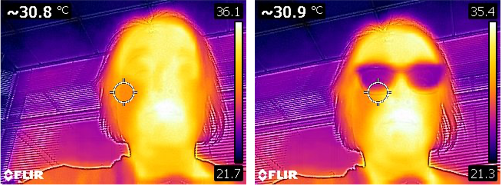
One of the fascinating things about light is that something transparent to one type of electromagnetic radiation may be opaque to another! For example, while glass (such as that used in eyeglasses) is transparent to visible light, it is opaque to infrared light. In Figure 26.12 (left), Dr. Pasquale took a selfie without her glasses on. Her entire face is “visible” to the IR camera, as infrared emitted as heat from her face is collected by the camera’s sensor. In Figure 26.12 (right), Dr. Pasquale took a similar selfie with her glasses on. Now her eyes appear dark, as the heat from behind the glass is blocked from reaching the camera’s sensor.
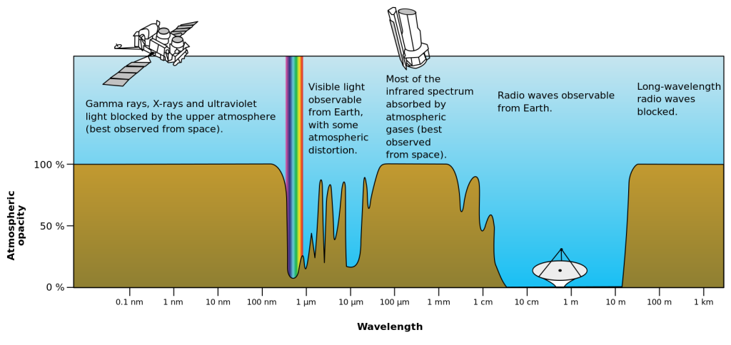
Similarly, our atmosphere is transparent to some types of light and opaque to others. This is why some radio waves can travel over long distances: they are reflected by the atmosphere. It’s also why satellites using microwaves can send information to our smartphones and GPS devices: the atmosphere is transparent to many microwave frequencies. Figure 26.13 shows the opacity of the Earth’s atmosphere to many different frequencies of electromagnetic radiation.
Further reading
- Finding the speed of light with peeps – Use your favorite marshmallow candy and a microwave to calculate the speed of light!
Practice questions
Conceptual comprehension
- What is the evidence that light does not need a material medium through which to travel? In other words, how do we know that light can travel through vacuum?
Numerical analysis
- Calculate the length of time it takes for an electromagnetic wave to travel from Earth to each of the following…
- …the Moon (which is
 , on average, away from the Earth).
 - …Mars (
 when Mars is closest to Earth).
 - …Voyager 1 (which was approximately
 away from Earth as of the time this question was written).
- …the Moon (which is
- Calculate the wavelength of an electromagnetic wave that has a frequency of 500 THz.
- Calculate the frequency of an electromagnetic wave that has a wavelength of 2 mm.
- Calculate the wavelength of the radio waves corresponding to the College of DuPage’s radio station, WDCB, which broadcasts at a frequency of 90.9 MHz.
- Calculate the frequency of red light having a wavelength of 633 nm.
Magnetism is a phenomenon that occurs when moving electric charges generate attractive and repulsive forces.
A circuit is an interconnection of elements such as batteries, light bulbs, resistors, capacitors, and diodes.
An electromagnetic wave is a transverse wave that contains electric and magnetic fields oscillating at right angles to each other.
In a transverse wave, the vibrations of the wave travel perpendicular to the direction of motion of the wave.
A wave is a periodic oscillation that transfers energy from one place to another.
Classical physics describes the natural phenomena that can be explained by Newton’s laws of motion, Maxwell’s equations, and the laws of thermodynamics.
A vector quantity is a variable that must be conveyed with both a numerical quantity (indicating magnitude or strength) and a direction.
Electromagnetism describes the interactions that occur between charged objects.
Mass is a property of physical objects that relates to resistance to changes in motion: inertia. (symbol: m, unit: kg)
Velocity is the vector quantity that describes the rate at which an object changes its position. Velocity is equal to displacement divided by time. (symbol: v, unit: m/s)
The electromagnetic spectrum describes the entire range of electromagnetic waves. Each subset of waves can be defined in different categories based on its frequency or wavelength.
Frequency describes how many oscillations occur per second in a wave. (symbol: f, unit: Hz)
The wavelength of a wave describes the shortest distance between two identical repeating points on a wave. (symbol: λ, unit: m)
Energy is defined as the capability of an object (or collection of objects) to do useful work. (symbol: E, unit: J)
Ionizing radiation refers to electromagnetic waves (UV, x-rays, and gamma rays) that contain sufficient energy to ionize atoms. These waves can cause damage to human DNA and other tissue.
A sound wave is a longitudinal wave that is caused by vibrations in air pressure between two points.
In a longitudinal wave, the oscillations of the wave travel in the same direction as the wave itself.
A vibration is a periodic back-and-forth motion that remains fixed in one location.
Transmission occurs when light waves pass through an object.
Wave amplitude describes the maximum displacement from either side of the equilibrium position.
Electromagnetic radiation is heat that is transferred from one place to another through light waves.
Heat is energy that is transferred from one object to another in response to a difference in temperature. (symbol: Q, unit: cal)
Science is the systematic pursuit of knowledge that comes about through asking questions, making careful observations, and carrying out experiments about how the universe works.
Technology is the outcome of using scientific principles to solve problems. This can be a product, innovation, or other object whose creation is based on science such as physics, chemistry, or biology.
Temperature defines the average kinetic energy of an object. It quantifies the “hotness” or “coldness” of something. (symbol: T, unit: °C or K)
Power quantifies how quickly work is done. (symbol: P, unit: W)
A crystalline solid has constituent atoms or molecules that are arranged in an orderly, repeating manner.
Radioactivity is the process by which an unstable nucleus releases energy and emits a particle.
Reflection occurs when a wave bounces off of a surface and subsequently changes its direction.
Refraction occurs when a wave changes speed (and therefore bends) at an interface between two different media.
Absorption of light occurs when light waves completely transfer their energy to a medium as they attempt to pass through it. The light is therefore blocked from transmitting through the medium.
An object is opaque if it does not allow any light to transmit through it.
An object is translucent if it allows light to pass through, but scatters that light in the process.
An object is transparent if it allows visible light to pass through without getting scattered or absorbed.
