23. Electric circuits
Summary
Voltage
Voltage is a property of electric circuits that’s very prevalent in our lives. Voltage has a symbol of the capital letter  . The symbol for voltage is the capital letter V, and the unit is the volt, which also has a symbol of the capital letter V, as described in the previous chapter of this textbook.
Voltage is a measure of electric potential, a property we discussed in the previous chapter. Usually, voltage is measured as a difference in electric potential between two points. This is why you may hear the term “potential difference” used in discussions of voltage.
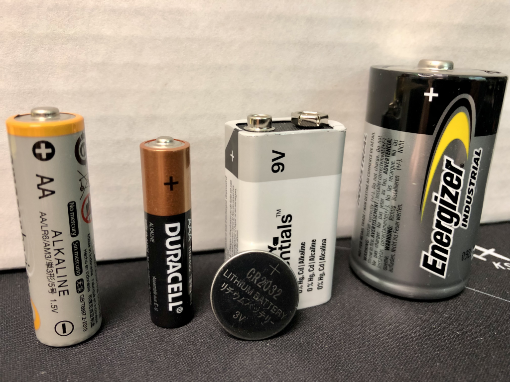
Voltage can be created in different manners. Chemical means can be used to separate positive and negative charges, for example, in a battery. A battery is a source of constant voltage. AA, AAA, and D-cell batteries are commonly used in household items like flashlights. These output a constant 1.5 volts. A 9-volt battery generates 9 volts of potential difference. Coin cell batteries used in smaller electronics like calculators usually generate either 1.5 volts or 3 volts. A selection of batteries is shown in Figure 23.1.
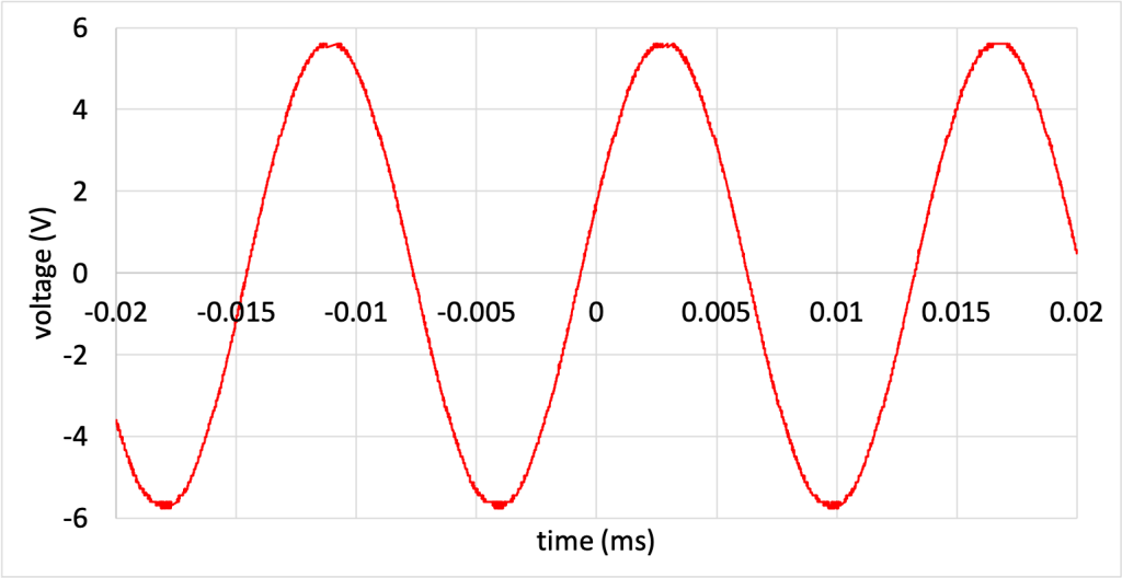
Alternatively, a generator can be used to produce voltage. Power plants generate electricity using a process we’ll discuss later in this textbook. The value of this voltage changes over time. In the United States, our power generation creates a voltage that fluctuates at a frequency of 60 hertz and that has an average voltage of 120 volts in our homes. A fluctuating voltage value is shown in Figure 23.2. (Download this data [XLSX, 171 kB]) It has the same general shape as the voltage we receive out of the electrical wall outlets in our homes.
Resistance
Resistance is the property of a material that impedes the flow of electrons throughout that material. The symbol for resistance is the capital letter  . The unit is the ohm, which has a symbol of the capital Greek letter Omega (
 ).
).
The resistance of a material is related to different properties of that material. One of the properties is the resistivity of that material. Resistivity has a symbol of the lowercase Greek letter rho ( ). The unit used for resistivity is m (an ohm times a meter). For pure substances, resistivity is a property inherent to that material. The smaller the resistivity of a material, the better conductor it is. For example, copper (an excellent conductor) has a resistivity of approximately
  at room temperature. On the other hand, quartz (which is a very good insulator) has a resistivity of
  .
.
Resistance is equal to the resistivity of an object times its length and divided by its surface area. In other words:

We can use this equation to determine the effects of each of these variables on resistance. The larger the resistivity, the larger the resistance. The longer the object, the larger the resistance. This makes sense as there is more material to move across. However, the larger the cross-sectional area, the smaller the resistance. This makes sense because a wider area offers more pathways for the electrons to move.
This equation is used to create electric circuit elements known as resistors. Resistors (see Figure 23.3) are used in electric circuits for many reasons: to create particular circuit properties and to amplify certain frequencies of electronic waves, among many other applications. They are frequently used by electrical and electronics engineers, and can be found in nearly all electric circuits.

Current and Ohm’s law
Current describes the flow of electric charge through a circuit. Current flows in a circuit when there is a complete path including a voltage source. Using a battery, this means there must be a complete path between the positive and negative ends of the battery.
The parts of an atom that are capable of moving through a conductor are the electrons. Electrons will flow in a closed path. Because an electron has a negative charge, electrons will be attracted to the positive end of a battery. Electron flow therefore goes from negative to positive in a circuit.
Current has a symbol of the capital letter  . The units used for current is the amp (A), short for ampere. One amp is equal to one coulomb per second. This means that one amp of current is equal to one coulomb of charge moving past a given point every second.
Note that current is defined by the movement of positive charge in a circuit. We now know that positive charges (protons) do not move freely. While this definition is technically incorrect, it has become a standard for scientists and engineers. Current flows from positive to negative in a circuit. This means that the direction of current is opposite to the direction of electron flow in a circuit.
The relationship between current, voltage, and resistance is given by Ohm’s law. Ohm’s law states that

In other words, the voltage of an element (such as a resistor or a light bulb) in a circuit equals the current through that circuit element times the resistance of that circuit element. Ohm’s law can be used to analyze an entire circuit or just to analyze particular sections or elements of a circuit. For example: Ohm’s law can be used to calculate the voltage over one particular resistor in a circuit that contains more than one resistor. It can also be used to calculate the voltage over multiple resistors in a circuit.
As an example, if a circuit that includes a voltage source of 9 volts contains a resistor of 5,000 ohms, how much current flows through the circuit? First, rearrange the variables in Ohm’s law to determine that current equals voltage divided by resistance. Then, solve for current.

Power
Power describes the rate at which energy is consumed in a circuit element. This is the same physical property that we discussed earlier in this textbook, which has a symbol of the capital letter  and units of watts. The equation for power in an electric circuit is

Power equals current times voltage.
Power can be generated in a circuit (batteries, power supplies, and generators can do this), and also consumed in a circuit (by resistors, light bulbs, and so on). Power is conserved, which means that all of the power consumed in a circuit is equal to all of the power generated in a circuit.
From a practical perspective, power is consumed by doing useful things in a circuit. An electric stove consumes electrical power and uses it to generate heat to cook food. A light bulb consumes electrical power and uses it to generate light. The tuning circuits in radios and televisions consume electrical power to allow us to listen to music or watch our favorite TV show. The electronics in your smartphone consume electrical power to operate the device.
Light bulbs are sold with a power rating in watts. That power rating tells us how much energy the light bulb will consume every second when it is in use. When comparing across identical types of light bulbs (for example, comparing between incandescent light bulbs), the power rating is proportional to the brightness of the light that the light bulb will emit. A photograph of multiple boxes of household light bulbs, and their power ratings, is shown in Figure 23.4 (on the left are incandescent light bulbs, on the right are LED light bulbs). Later in this textbook, we will discuss the different types of light emission used to create these light bulbs, and why exactly the incandescent light bulbs have larger power ratings than LED lights.
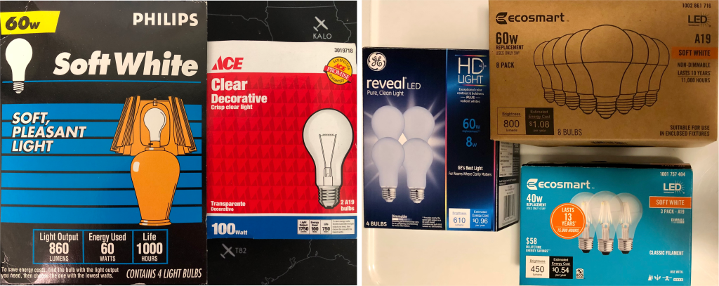
For now, it is sufficient to point out that incandescent light bulbs have larger power ratings than LED light bulbs of similar brightness due to the fact that incandescent light bulbs generate a lot of heat. Some of the electrical power going into the incandescent light bulbs will be emitted as light, with the rest being emitted as heat. LED light bulbs are much more efficient at converting electric energy to light. Furthermore, LED light bulbs tend to last longer than incandescent light bulbs. This efficiency is better for the environment and saves us money on our electric bills.
Speaking of electric bills, if you have ever paid one, you have probably noticed that the units used in the bills are kilowatt-hours. This is a unit of energy. Energy equals power times time. Because kilowatt is a unit of power, and hours are a unit of time, a kilowatt-hour is a unit of energy. One kilowatt-hour is equal to consuming one thousand watts of power during the time period of an entire hour.
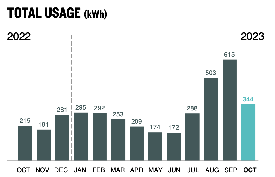
Our electric bills charge us for the electrical energy we consume every month. For reference, Figure 23.5 shows the electrical energy used by Dr. Pasquale in one year, split into months. Note that she uses more electrical energy in the summer when running an air conditioner to cool her home, and less electrical energy in the winter, when she uses natural gas (a different source of energy) to heat her home.
Circuits
A circuit is a closed path where current flows. Circuits can consist of different circuit elements: voltage sources (such as batteries), resistors, light bulbs, motors, and so on. Some circuits have only a few elements. Some circuits have many elements and are much more complicated. All of the circuits described in this textbook can be analyzed using Ohm’s law, conservation of energy, and conservation of charge. Electrical engineers take classes in circuit analysis to learn how to design circuits with specific properties.
Circuit diagrams
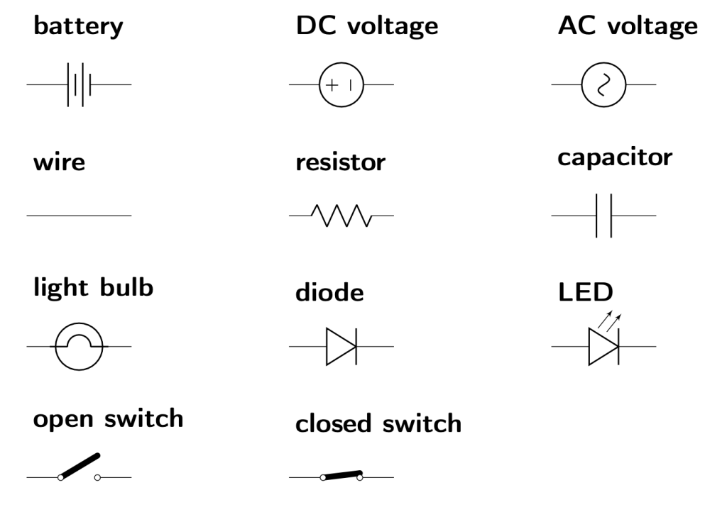
A circuit can be drawn as a circuit diagram. This uses symbols for each circuit element (shown in Figure 23.6) to represent how the circuit is connected. A circuit diagram acts as a kind of “blueprint” for an engineer or technician to build or fix a circuit, or to learn about how a circuit works.
For example, a simple circuit can consist of a battery and a resistor, with wires used to connect the battery and resistor in a closed path. The diagram of this circuit is shown in Figure 23.7. If the battery and resistor have particular values, those values would be included on the circuit diagram next to the corresponding circuit element’s symbol.
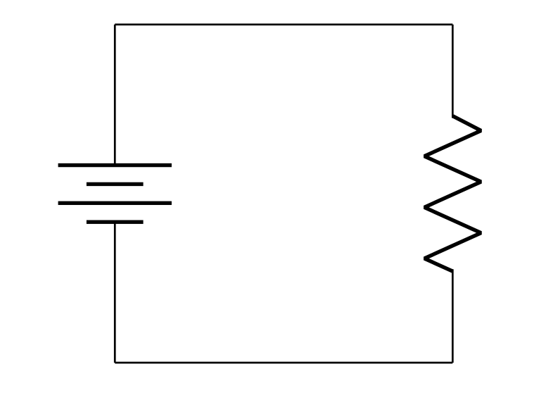
Given this circuit diagram (and knowing the value of the battery and resistor), we could then use Ohm’s law to calculate the value of the current through the resistor and the power equation to determine how much power is output from the battery and therefore consumed by the resistor.
While there are many different types of circuits, for the purposes of this textbook, the two primary configurations of circuit elements are series and parallel.
Series circuits
A series circuit is one where all of the circuit elements are contained in a single path. (It is possible to have a more complicated arrangement of circuit elements, but in this case, we will only consider single elements that are all arranged in series.) Because there is only one path, current must flow through all of the elements contained in that path. Due to conservation of charge, every element in that path will experience the same amount of current because any charge that flows into a circuit element must flow out.
Because there is only one path for current to flow through, when two or more circuit elements (such as the light bulbs) are connected in series, if one of them becomes broken or disconnected and disrupts the flow of current, the other circuit elements will also become disconnected.
Consider the series circuit consisting of a battery and two light bulbs, as shown in Figure 23.8.
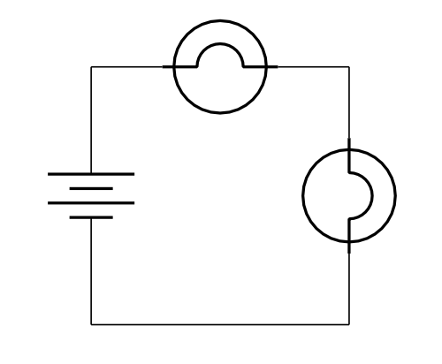
In the video below, Dr. Pasquale demonstrates this. When she removes one of the light bulbs from the circuit, the other one turns off. This is true regardless of which light bulb is disconnected from the circuit. As soon as the light bulb is connected again, the light bulbs turn on again. (Note that the battery is not shown in the video, but is connected to the light bulbs by the thick red and black wires.)
Many cheap holiday lights are like this. If one of the light bulbs breaks, the rest of the light bulbs turn off as well. Dr. Pasquale demonstrates this in the video below by removing one of the light bulbs in a strand of holiday lights by taking one of the light bulbs out. This turns off all of the other light bulbs in the strand of lights.
In a series circuit consisting of two or more resistors, because current will be forced to flow through all of the resistors in order to travel through the circuit, the total resistance of the circuit will be greater than the resistance of any of the individual resistors. In a series circuit, the total resistance of the circuit is equal to the sum of each individual resistor in the circuit. That is,

Due to conservation of energy, the voltage experienced by each resistor in a series circuit (containing two or more resistors) will be smaller than the voltage of the battery. If two series resistors have the same value, then the voltage drop over each resistor will be one half the battery voltage. If three series resistors have the same value, the voltage drop over each one will be one third the battery voltage.
In a series circuit with unequal resistor values, the resistor with the largest resistance value will have the largest voltage drop. This is because the current in a series circuit is equal throughout the circuit (as mentioned above), and Ohm’s law states that voltage is proportional to resistance, all other things being equal. Each individual voltage drop will be equal to the current through the series circuit multiplied by the resistance of the individual resistor, as described by Ohm’s law.
Regardless of the values of the number of resistors or resistance values of each resistor, the individual voltage drops over each resistor will be equal to the voltage provided by the source. That is,

Consider a series circuit consisting of a 6 V battery and three identical resistors, shown in Figure 23.9.
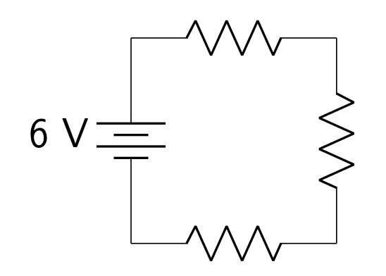
In the video below, Dr. Pasquale has built this circuit. She uses a device called a multimeter to measure the voltage that the battery produces (6 V), and the voltage over each individual resistor. Each resistor has a voltage drop of 2 V, shown by the multimeter, verifying that the voltage is evenly split between the identical resistors.
It is possible to calculate how much power is consumed by each resistor in a series circuit by using a combination of Ohm’s law and the power equation. In the power equation, the individual voltage of each resistor is not necessarily known. However, we know from Ohm’s law that the voltage of any individual circuit element is equal to the current through that element times the resistance of that element. This allows us to calculate that

That is, in a series circuit, the power consumed by any individual resistor is equal to the current through the circuit, squared, times the resistance of the individual resistor. We can calculate the current through the circuit by using Ohm’s law. The current will be equal to the voltage source divided by the sum of all of the resistances in the circuit:

Parallel circuits
A parallel circuit is one where circuit elements are all contained in their own path in the circuit. In other words, they are connected end-to-end, hence the name parallel. Because of conservation of energy, each circuit element that is connected in parallel will experience the same amount of voltage. If they are connected in parallel with a battery or voltage source, then that voltage will be equal to the battery or source voltage.
Because there are multiple paths for current to flow, when two or more circuit elements are connected in parallel, if one of them becomes broken or disconnected, the other circuit elements will continue to function normally.
Consider the parallel circuit consisting of a battery and two light bulbs, as shown in Figure 23.10.
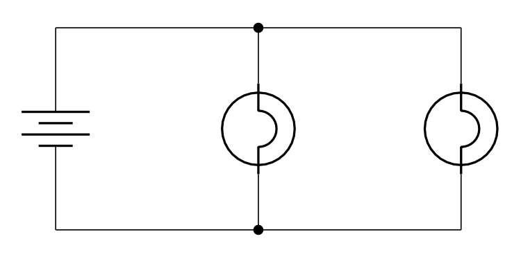
In the video below, Dr. Pasquale demonstrates this circuit. When she removes one of the light bulbs from the circuit, the other one remains illuminated. This is true regardless of which light bulb is disconnected from the circuit. (Note that the battery is not shown in the video, but is connected to the light bulbs by the thick red and black wires.)
An example of a parallel configuration of circuit elements would be our homes. They are wired in parallel. If you turn off the kitchen light, your refrigerator is still able to continue working. (Note that some aspects of home wiring are in series, which is why light switches can be used to turn off lights. But just because you turn off the lights with a switch does not mean that power is disconnected to other parts of your home.)
In a parallel circuit consisting of two or more resistors, because current can divide up and flow through multiple paths as it travels through the circuit, the total resistance of the circuit will be less than the resistance of any of the individual resistors. In a parallel circuit, the reciprocal of the total resistance of the circuit is equal to the sum of the reciprocal of each individual resistor in the circuit. That is,

This equation confirms the statement above that the total resistance decreases in a parallel circuit (when compared to each individual resistor value).
Due to conservation of charge, the current through each resistor in a parallel circuit (containing two or more resistors) will be smaller than the current through the battery. If two parallel resistors have the same value, then the current through each resistor will be one half the current through the battery. If three parallel resistors have the same value, then the current through each resistor will be one third of the current through the battery.
In a parallel circuit with unequal resistor values, the resistor with the largest resistance value will have the smallest current. This is because the voltage in a parallel circuit is equal throughout the circuit (as mentioned above), and Ohm’s law states that current is inversely proportional to resistance, all other things being equal. Each individual current will be equal to the voltage across the parallel circuit divided by the resistance of the individual resistor, as described by Ohm’s law.
Regardless of the values of the number of resistors or resistance values of each resistor, the individual currents through each resistor will be equal to the current provided by the source. That is,

Consider a parallel circuit consisting of a battery and three identical resistors, shown in Figure 23.11. (In this case, it does not necessarily matter what the voltage of the battery is.)
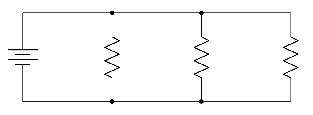
In the video below, Dr. Pasquale has built this circuit. She uses a multimeter to measure the current that flows through the battery (1.8 mA), and the current through each individual resistor. Each resistor has a current of 0.6 mA, shown by the multimeter, verifying that the current is evenly split between the identical resistors.
It is possible to calculate how much power is consumed by each resistor in a parallel circuit by using a combination of Ohm’s law and the power equation. In the power equation, the individual current through each resistor is not necessarily known. However, we know from Ohm’s law that the current through any individual circuit element is equal to the voltage over that element divided by the resistance of that element. This allows us to calculate that

That is, in a parallel circuit with all circuit elements wired in parallel with the battery or voltage source, the power consumed by any individual resistor is equal to the voltage source of the circuit, squared, divided by the resistance of the individual resistor.
Open circuits
In an open circuit, there is no complete path for current to flow. Electrons do not move, and none of the circuit elements will operate. A switch can cause an open circuit. Sometimes this is useful, for example, when we want to turn the lights off in our bedrooms to go to sleep at night. A switch opens the circuit and prevents current from flowing through the lights.
A circuit consisting of a battery, switch, and a light bulb will be a closed circuit when the switch is closed (Figure 23.12, left). In this configuration, current will flow and the light bulb will light up. When the switch is opened, the circuit is an open circuit, no current will flow, and the light bulb will turn off (Figure 23.12, right).
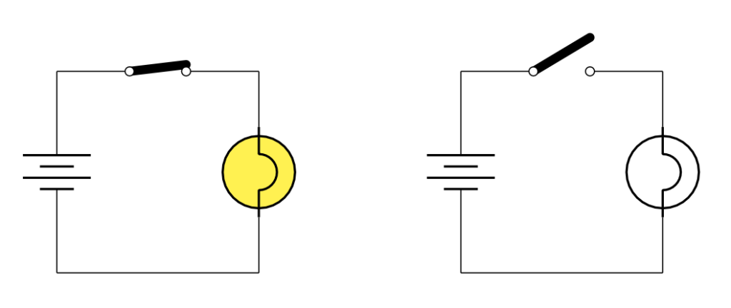
This circuit is demonstrated in the video below. Dr. Pasquale starts with the circuit from Figure 23.12 with the switch closed, and the light bulb is illuminated. When she opens the switch, current no longer flows and the light bulb turns off. (Note that the battery is not shown in the video below, but is connected with the thick red and black wires.)
Short circuits
A short circuit is a circuit with a very low resistance path that electrons can take. Electrons will proportionally travel through the path of least resistance. If there is a path of zero resistance, such as with a wire (which does not have exactly zero resistance, but its resistance is extremely small), then all (or most all) current will flow through that path. Because resistance is very low, current will become extremely high. If current becomes very high, so will power. This can cause a lot of heating, and eventually, wires and other circuit elements can melt. Short circuits can be very dangerous, and electrical engineers learn how to spot short circuits and avoid them when building circuits.
Consider the circuit in Figure 23.13 containing a battery, a light bulb, a switch, and wires to connect the circuit elements together. The light bulb and the switch are all connected in parallel with the battery.
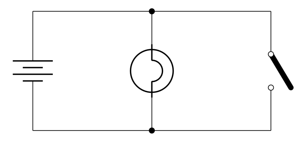
In the video below, Dr. Pasquale uses the switch to cause a short circuit in the circuit from Figure 23.13, creating a low-resistance path that bypasses the light bulb. (When a switch is closed, it acts like a wire.) Note that the battery is not shown in the video, but is connected to the circuit through the thick red and black wires. When Dr. Pasquale closes the switch, current flows through the switch instead of through the light bulb, causing the light bulb to turn off. Dr. Pasquale can’t keep the switch closed for too long, as the short circuit will drain the battery in a short amount of time. The wires and switch will also heat up, possibly melting the wires if it is left in this condition for too long.
Alternating and direct current
The voltage and current in a circuit can exhibit one of two different properties. One possibility is that the voltage and current stay constant over time. This is known as direct current or DC. In a DC circuit, our measurements of voltage and current will stay the same.
Batteries are capable of producing a DC voltage. AA batteries generate a constant 1.5 V. Most consumer electronics require DC to either function or to charge their batteries. Most of these devices contain a converter that generates the correct DC voltage to carry this out. (The basics of this converter will be explained at the end of this chapter.)
On the other hand, it is possible for voltage and current signals to change over time. Usually they will oscillate in a sinusoidal pattern, like a wave (as shown above in Figure 23.2). This is known as alternating current or AC. A device known as an oscilloscope can be used to record how voltage changes over time. This data was used to create the graph shown in Figure 23.2 which shows the voltage plotted with respect to time.
For reasons we’ll discuss in a later chapter of this textbook, power plants generate alternating current. The wall outlets in our home therefore provide AC signals. The frequency of the voltage oscillation is 60 Hz in the United States, and the average value of the voltage is 120 V in the US. When traveling to other countries, it is important to bring an adapter to ensure that our electronic devices continue to function when plugged in to different values or frequencies of voltage.
Diode: one-way valve
A diode is a circuit element that acts like a one-way valve. A diode only allows current to flow through in one direction. (On the circuit diagram, the direction that current can flow is in the same direction that the triangle points.) When connected in a DC circuit, a diode can prevent current from flowing if it is connected backwards. A light-emitting diode, LED, is a diode that also emits light. When connected into a circuit in the forward direction, current flows through and the LED lights up. When connected backwards, current is blocked and the LED remains off. This is shown in the video below. (Note that the voltage source is not shown in the video.)
In an AC circuit, a diode allows current to flow in only one direction. It transmits through the positive current and blocks the negative current. We can see this effect in the video below as the LED only lights up when it allows current to flow through, every half cycle.
A circuit (shown as a circuit diagram in Figure 23.14) built with a regular diode (one that does not emit light) will block negative voltages from the AC signal.
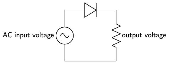
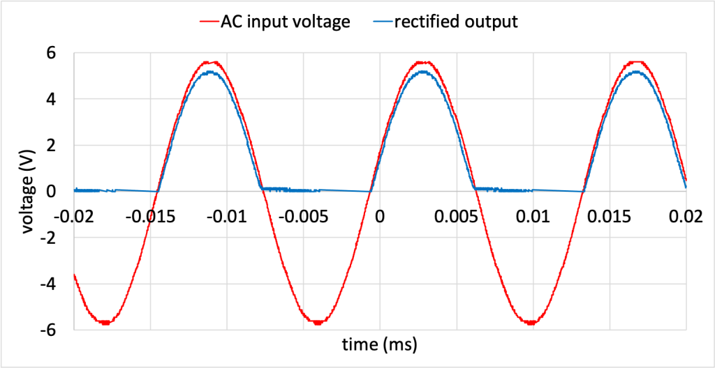
This circuit was built by Dr. Pasquale, and the input and output voltages were recorded on an oscilloscope and plotted in Figure 23.15. (Download this data [XLSX, 210 kB]) The AC input signal is red, and the output signal, after negative voltages have been blocked, is shown in blue. This circuit is called a rectifier. A rectifier is a circuit that only allows current to flow in one direction.
Full-wave rectifier
Because every half cycle, the diode in Figure 23.14 blocks current, this would not be an efficient circuit to convert AC to DC. For that we can use a circuit called a full-wave rectifier. The configuration of diodes in a full-wave rectifier circuit (shown in Figure 23.16 as a circuit diagram) causes current to always flow through in one direction.
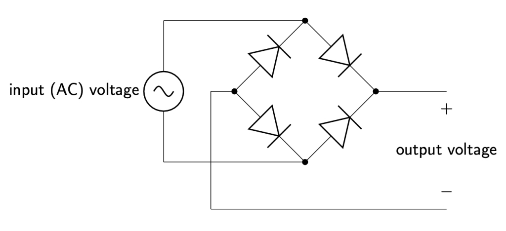
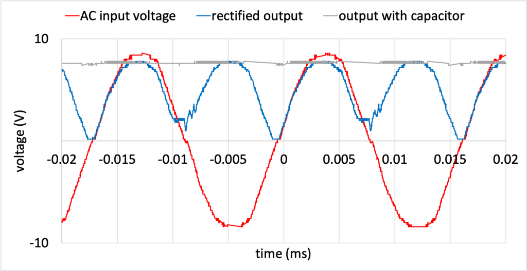
Figure 23.17 shows the AC input voltage (red curve) and the rectified output (blue curve). (Download this data [XLSX, 245 kB]) The output voltage is changing (so it is still AC), but it is now always positive. (The first half of the video below shows this same circuit.)
Capacitor
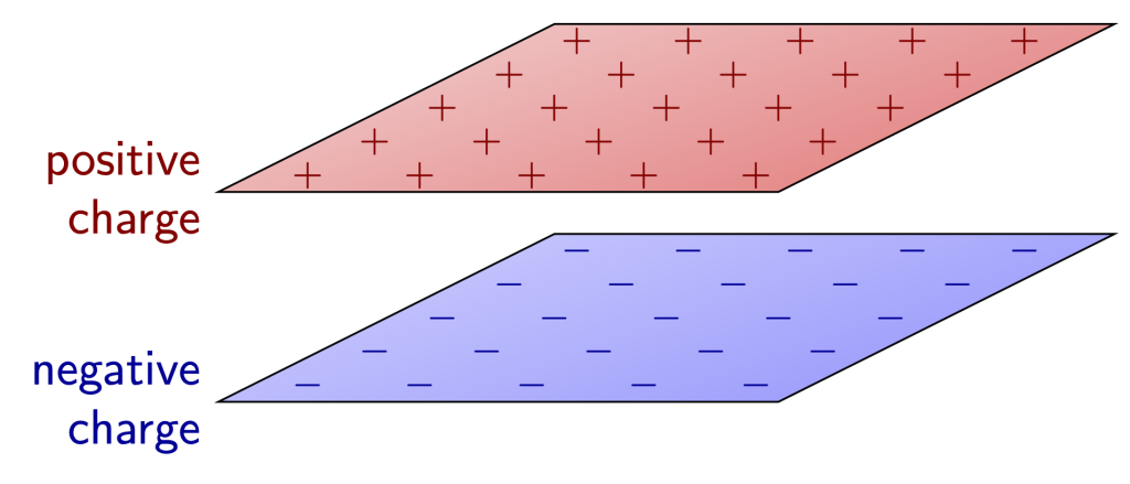
To smooth out the oscillations in this output voltage and to obtain a nice smooth DC voltage, we use a device called a capacitor. In its simplest form, a capacitor is created from two plates of conducting material that allow equal and opposite charge to build up on them, as shown in Figure 23.18. In between the two plates is an insulator (charge cannot flow between the two plates through this insulator). When connected to a power source, positive charge will build up on one plate and negative charge will build up on the other plate. This leads to a storage of electric potential energy, which can be utilized if the power supply is later removed or disconnected from the circuit.
Because a capacitor stores electric potential energy, it is capable of smoothing out changes in voltage in a circuit. This forms the basis of the converters used to charge DC-powered electronics that obtain power from a wall outlet. In the video below, Dr. Pasquale adds a capacitor to the full-wave rectifier, and the oscilloscope output shows the AC signal converting to a constant DC value. This data was measured and recorded in Figure 23.17, above, in the gray curve.
Further reading
- Resistor color codes (4-band) [PDF, 52 kB] – This chart explains how to read the colored stripes on a 4-band resistor to determine its resistance.
- Voltage, current, resistance, and Ohm’s law – This website tutorial from SparkFun explains the basics of the concepts that are introduced in this textbook chapter.
- Why is it when one light goes out, they all go out? – So THAT Explains It! – Episode 12 – Dr. Pasquale contributed to this video as part of the “So That Explains It!” video series at the College of DuPage to explain why holiday lights stop working when one of the light bulbs in a strand breaks.
Practice questions
Conceptual comprehension
- Consider the series circuit containing two light bulbs (call them A and B), shown in Figure 23.8, and the parallel circuit containing two light bulbs (call them C and D), shown in Figure 23.10. If these circuits are both built with an identical voltage source and identical light bulbs, compare the brightness of each of the four light bulbs…
- …will A and B have the same or different brightness? Why?
- …will C and D have the same or different brightness? Why?
- …will the series light bulbs have a different level of brightness than the parallel light bulbs? Why or why not?
- In a series circuit with three light bulbs, if one light bulb burns out, what happens to the brightness of the other light bulbs? How does this compare to a similar situation in a parallel circuit?
- When you add more light bulbs to a series circuit, how does it affect the overall brightness of the light bulbs in the circuit compared to adding more light bulbs to a parallel circuit with the same power supply?
Numerical analysis
- A resistor with a resistance of 100 ohms is connected to a 3 V battery. Calculate the current through the resistor.
- If a 12 V battery is connected to a circuit, and the current in the circuit is 0.5 A, calculate the resistance of the circuit elements.
- A light bulb has a resistance of 60 ohms. Calculate the voltage that is required to make it draw a current of 0.12 A.
- If a circuit element is connected to a 120 V power source and draws a current of 5 A, calculate the power consumed by the device.
- A 60 W light bulb is connected to a 240-volt power source. Calculate the current through the light bulb.
- In a circuit, a resistor with a resistance of 40 ohms is connected to a 6 V battery. Calculate the power consumed by the resistor.
- A series circuit consists of two resistors with values of 800 ohms and 1200 ohms. They are connected to a 10 V battery. Calculate…
- …the total resistance of the circuit.
- …the power consumed by the 800 ohm resistor.
- …the power consumed by the 1200 ohm resistor.
- In a series circuit, three resistors with values of 10 ohms, 15 ohms, and 20 ohms are connected in series with a 5 V battery. Calculate…
- …the total resistance of the circuit.
- …the power consumed by the 10 ohm resistor.
- …the power consumed by the 15 ohm resistor.
- …the power consumed by the 20 ohm resistor.
- In a parallel circuit, two identical 100 ohm resistors are connected to a 5 V power source, creating a total current of 0.1 A flowing through the source. Calculate…
- …the current through each resistor.
- …the power consumed by each resistor.
Hands-on experiments
- If you have one or two AA or AAA batteries, a small light bulb, and some wire, connect the wires and the light bulb in series with the battery. The light bulb should illuminate. If you have two batteries, connect them together in series with the light bulb and see how that affects the brightness of the light bulb. If you have different bulb sizes, try them out and see how it affects the circuit. (Note: this experiment will not work with household light bulbs, which generally require 120 V to work.)
- If you have two AA or AAA batteries, an LED, and some wire, connect the circuit elements together in series and see how the LED must be connected to allow current to flow. Flip the LED backwards and see what happens.
Voltage is a difference in electric potential between two points in a circuit. It can be considered as a "push" that causes current to flow. (symbol: V, unit: V)
A circuit is an interconnection of elements such as batteries, light bulbs, resistors, capacitors, and diodes.
Electric potential describes the amount of work it takes to move a charge through an electric field divided by the amount of charge. (symbol: EP, unit: V)
Electric charge is a fundamental property of matter that causes particles that carry a charge to experience a force when in the presence of an electric field.
A generator converts mechanical work to electrical energy.
Frequency describes how many oscillations occur per second in a wave. (symbol: f, unit: Hz)
Resistance is the property of a material that impedes the flow of electrons throughout that material. (symbol: R, unit: Ω)
An electron is a fundamental building block of matter that has a negative charge and is found surrounding the nucleus of an atom.
In a pure substance, the properties of a substance (density, melting point, specific heat capacity, etc.) are inherent to the material.
A wave is a periodic oscillation that transfers energy from one place to another.
Current describes the flow of electric charge through a circuit. (symbol: I, unit: A)
A proton is a subatomic particle that has a positive charge and resides in the nucleus of an atom.
Ohm's law describes the relationship between voltage, resistance, and current in an electric circuit. Ohm's law states that V = IR.
Power quantifies how quickly work is done. (symbol: P, unit: W)
Energy is defined as the capability of an object (or collection of objects) to do useful work. (symbol: E, unit: J)
Heat is energy that is transferred from one object to another in response to a difference in temperature. (symbol: Q, unit: cal)
Efficiency quantifies how well work input is converted to work output. (symbol: e, unit: none)
A motor converts electrical energy to mechanical work.
A series circuit is one where all of the circuit elements are contained in a single path.
A parallel circuit is one where circuit elements are all contained in their own path in the circuit.
A short circuit is a circuit that contains a very low-resistance path along which electrons will travel. It can result in excess current, which may cause the circuit to overheat.
Melting is the phase change that occurs when a substance converts from a solid to a liquid.
Direct current (DC) is a property of a voltage or current source in which the value of the voltage or current remains constant over time.
Alternating current (AC) is a property of a voltage or current source in which the value of the voltage or current changes periodically with time.
A diode is a circuit element that acts like a one-way valve in that it only allows current to flow in one direction but not the other.
A capacitor is a circuit element that stores energy in the form of an electric field. It is commonly used in circuits to smooth out changes in voltage to create a DC signal.
